


96
Oil Specification —
If oil is added, it must meet the fol-
lowing Carrier specifications:
Oil Type for units using R-134a . . . . . . . . . . . . . . . . . .Inhibited
polyolester-based synthetic
compressor oil formatted for
use with HFC, gear-driven,
hermetic compressors.
ISO Viscosity Grade . . . . . . . . . . . . . . . . . . . . . . . . . . . . . . . . 68
The polyolester-based oil (P/N: PP23BZ103) may be
ordered from your local Carrier representative.
Oil Changes —
Carrier recommends that a yearly oil
analysis be performed to determine when to change oil and
when to perform a compressor inspection. However, if yearly
analysis is not performed or available, the time between oil
changes should be no longer than 5 years.
TO CHANGE THE OIL
1. Transfer the refrigerant into the chiller condenser vessel
(for isolatable vessels) or to a pumpout storage tank.
2. Mark the existing oil level.
3. Open the control and oil heater circuit breaker.
4. When the chiller pressure is 5 psig (34 kPa) or less, drain
the oil reservoir by opening the oil charging valve
(Fig. 2 and 3). Slowly open the valve against refrigerant
pressure.
5. Change the oil filter at this time. See Changing Oil Filter
section.
6. Change the refrigerant filter at this time, see the next sec-
tion, Refrigerant Filter.
7. Charge the chiller with oil. Charge until the oil level is
equal to the oil level marked in Step 2. Turn on the power
to the oil heater and let the PIC II warm it up to at least
140 F (60 C). Operate the oil pump manually, using the
Control Test function, for 2 minutes. For shutdown condi-
tions, the oil level should be full in the lower sight glass.
If the oil level is above
1
/
2
full in the upper sight glass, re-
move the excess oil. The oil level should now be equal to
the amount shown in Step 2.
Refrigerant Filter —
A refrigerant filter/drier, located on
the refrigerant cooling line to the motor, should be changed
once a year or more often if filter condition indicates a need for
more frequent replacement. Change the filter by closing the fil-
ter isolation valves (Fig. 2 and 3) and slowly opening the flare
fittings with a wrench and back-up wrench to relieve the pres-
sure. A moisture indicator sight glass is located beyond this fil-
ter to indicate the volume and moisture in the refrigerant. If the
moisture indicator indicates moisture, locate the source of wa-
ter immediately by performing a thorough leak check.
Oil Reclaim Filter —
The oil reclaim system has a
strainer on the eductor suction line, a strainer on the discharge
pressure line, and a filter on the cooler scavenging line. Re-
place the filter once every 5 years or when the machine is
opened for service. This filter does not contain desiccant for
moisture removal, so changing the filter will not change the
moisture indicator status. Change the filter by closing the filter
isolation valves and slowly opening the flare fitting with a
wrench and back-up wrench to relieve the pressure. Change the
strainers once every 5 years or whenever refrigerant is evacuat-
ed from the cooler.
Inspect Refrigerant Float System —
Perform this
inspection only if the following symptoms are seen.
• There is a simultaneous drop in cooler pressure and
increase in condenser pressure. This will be accompa-
nied by an increase in kW/Ton.
• The liquid line downstream of the float valve feels warm.
This indicates condenser gas flowing past the float. An
increase in kW/Ton will also occur.
1. Transfer the refrigerant into the cooler vessel or into a
pumpout storage tank.
2. Remove the float access cover.
3. Clean the chamber and valve assembly thoroughly. Be
sure the valve moves freely. Ensure that all openings are
free of obstructions.
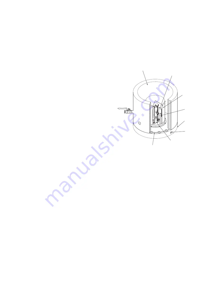
4. Examine the cover gasket and replace if necessary. See
Fig. 50 for a view of the float valve design. Inspect the
orientation of the float slide pin. It must be pointed to-
ward the bubbler tube for proper operation.
ECONOMIZER FLOAT SYSTEM (TWO-STAGE COM-
PRESSORS) — For two-stage compressors, the economizer
has a low side ball type float system. The float refrigerant level
can be observed through the two sight glasses located on the
float cover under the condenser. See Fig. 51 for float detail. In-
spect the float every five years. Clean the chamber and the float
valve assembly. Be sure that the float moves freely and the ball
bearings that the float moves on are clean.
ECONOMIZER DAMPER VALVE (TWO-STAGE COM-
PRESSORS) — The damper valve should be inspected every
5 years or when the condenser is opened for service. With the
refrigerant transferred, remove the spring housing from the
valve (Fig. 52). The valve spring will exert 50 lb force upward.
Check the valve and linkage for free travel and loose parts.
Clean the assembly thoroughly. Replace the valve packing and
the housing O-ring if necessary.
Inspect Relief Valves and Piping —
The relief valves
on this chiller protect the system against the potentially danger-
ous effects of overpressure. To ensure against damage to the
equipment and possible injury to personnel, these devices must
be kept in peak operating condition.
1
2
3
4
5
6
7
8
LEGEND
Fig. 50 — 19XR/XRV Float Valve Design
1
— Refrigerant Inlet from FLASC Chamber
2
— Linear Float Assembly
3
— Float Screen
4
— Bubbler Line
5
— Float Cover
6
— Bubbler Line Connection
7
— Refrigerant Outlet to Cooler
8
— Gasket
a23-1632
Содержание AquaEdge 19XR series
Страница 69: ...69 Fig 33 19XR Leak Test Procedures a19 1625 ...
Страница 150: ...150 Fig 62 PIC II Control Panel Wiring Schematic Frame 2 3 4 and E Compressors without Split Ring Diffuser a19 1870 ...
Страница 152: ...152 a19 1871 Fig 63 PIC II Control Panel Wiring Schematic Frame 4 and 5 Compressors with Split Ring Diffuser ...
Страница 154: ...154 Fig 64 Benshaw Inc Wye Delta Unit Mounted Starter Wiring Schematic Low Voltage a19 1873 ...
Страница 161: ...161 Fig 69 Typical Low Voltage Variable Frequency Drive VFD Wiring Schematic 575 v ...
Страница 162: ...162 Fig 69 Typical Low Voltage Variable Frequency Drive VFD Wiring Schematic 575 v cont ...
Страница 163: ...163 Fig 69 Typical Low Voltage Variable Frequency Drive VFD Wiring Schematic 575 v cont a19 1880 ...
Страница 176: ...176 CONTINUED ON NEXT PAGE Fig 71 Typical Medium Voltage Variable Frequency Drive VFD Wiring Schematic cont a19 2064 ...
Страница 186: ...186 APPENDIX B LEAD LAG WIRING 19XR Lead Lag Schematic Series Cooler Flow a19 1655 ...
Страница 187: ...187 APPENDIX B LEAD LAG WIRING cont 19XR Lead Lag Schematic Parallel Cooler Flow a19 1717 ...