


83
GUIDE VANE ACTUATOR CALIBRATION — This au-
tomated procedure is performed at the factory prior to new
chiller shipment. During this test, the CCM outputs a discrete
24-v signal from terminal J11 to fully open and fully close the
guide vanes. A 0.1 to 3.0 V nominal signal is fed back to the
terminals J4-9 and J4-10 to indicate the position of the guide
vanes to the CCM. This calibration will need to be repeated if
the guide vane actuator or ICVC controller is replaced, or if
new controller software is downloaded. A prestart alert mes-
sage will remind the user prior to the next start-up if this has not
been done.
Select the last item in the Controls Test menu. Press YES to
proceed with calibration per the prompt. The guide vanes will
close fully, then open to 100% (regardless of the position con-
figured at maximum opening). The system will store voltages
corresponding to 0% and 100%, then indicate the the calibra-
tion is complete.
NOTE: Enter guide vane calibration to calibrate guide
input on CCM (Plug J4 upper terminal 9 and 10).
NOTE: If during the control test the guide vanes do not open,
verify the low pressure alarm is not active. (An active low
pressure alarm causes the guide vanes to close.)
NOTE: The oil pump test will not energize the oil pump if
cooler pressure is below –5 psig (–35 kPa).
When the control test is finished or the
softkey is
pressed, the test stops, and the CONTROL TEST menu dis-
plays. If a specific automated test procedure is not completed,
access the particular control test to test the function when ready.
The CONTROL TEST menu is described in the Table 15.
COOLER AND CONDENSER PRESSURE TRANS-
DUCER AND WATERSIDE FLOW DEVICE CALIBRA-
TION (WATERSIDE DEVICE OPTIONAL WITH CCM
INPUTS AVAILABLE) — Calibration can be checked by
comparing the pressure readings from the transducer to an
accurate refrigeration gage reading. These readings can be
viewed or calibrated from the HEAT_EX screen on the CCM.
The transducer can be checked and calibrated at 2 pressure
points. These calibration points are 0 psig (0 kPa) and between
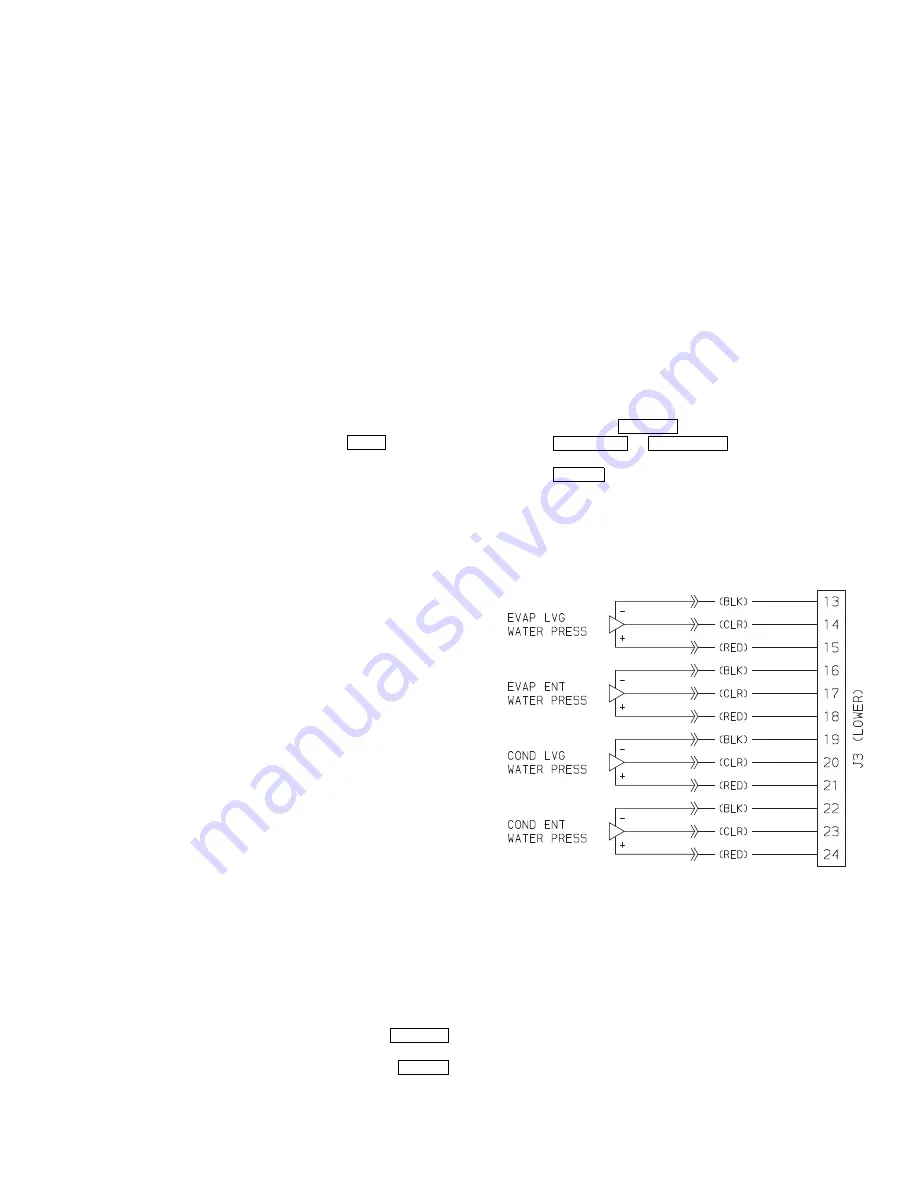
25 and 250 psig (173 and 1724 kPa). Wiring is shown in
Fig. 42. To calibrate these transducers:
1. Shut down the compressor and the cooler and condenser
pumps.
NOTE: There should be no flow through the heat
exchangers.
2. Disconnect the transducer in question from its Schrader
fitting for cooler or condenser transducer calibration. For
oil pressure or flow device calibration keep transducer in
place.
NOTE: If the cooler or condenser vessels are at 0 psig
(0 kPa) or are open to atmospheric pressure, the transduc-
ers can be calibrated for zero without removing the trans-
ducer from the vessel.
3. Access the HEAT_EX screen and view the particular
transducer reading (the
EVAPORATOR PRESSURE
or
CONDENSER PRESSURE
parameter on the HEAT_EX
screen). To calibrate oil pressure or waterside flow de-
vice, view the particular reading (
CHILLED WATER
DELTA P
and
CONDENSER WATER DELTA P
on the
HEAT_EX screen and
OIL PUMP DELTA P
on the
COMPRESS screen). It should read 0 psi (0 kPa). If the
reading is not 0 psi (0 kPa), but within ±5 psi (35 kPa),
the value may be set to zero by pressing the
softkey while the appropriate transducer parameter is
highlighted on the ICVC screen. Then press the
softkey. The value will now go to zero. No high end cali-
bration is necessary for
OIL PUMP DELTA P
or flow
devices.
If the transducer value is not within the calibration range,
the transducer will return to the original reading. If the
pressure is within the allowed range (noted above), check
the voltage ratio of the transducer. To obtain the voltage
ratio, divide the voltage (dc) input from the transducer by
the supply voltage signal (TRANSDUCER VOLTAGE
REF displayed in CONTROL TEST menu in the CCM
PRESSURE TRANSDUCERS screen) or measure
across the positive (+ red) and negative (– black) leads of
the transducer. For example, the condenser transducer
voltage input is measured at CCM terminals J2-4 and J2-
5. The voltage ratio must be between 0.80 and 0.11 for
the software to allow calibration. Rotate the waterside
flow pressure device from the inlet nozzle to the outlet
nozzle and repeat this step. If rotating the waterside flow
device does not allow calibration then pressurize the
transducer until the ratio is within range. Then attempt
calibration again.
4. A high pressure point can also be calibrated between 25
and 250 psig (172.4 and 1723.7 kPa) by attaching a regu-
lated 250 psig (1724 kPa) maximum pressure (usually
from a nitrogen cylinder). The high pressure point can be
calibrated by accessing the appropriate transducer param-
eter on the HEAT_EX screen, highlighting the parameter,
pressing the
softkey, and then using
the
or
softkeys to adjust the
value to the exact pressure on the refrigerant gage. Press
the
softkey to finish the calibration. Pressures at
high altitude locations must be compensated for, so the
chiller temperature/pressure relationship is correct.
The PIC II does not allow calibration if the transducer is too
far out of calibration. In this case, a new transducer must be
installed and recalibrated.
OPTIONAL THERMAL DISPERSION FLOW SWITCH
CALIBRATION — Set the flow through the water circuit to
the minimum safe flow that will be encountered.
Reduce the sensitivity of the switch by turning the adjust-
ment counter-clockwise until the yellow LED turns off. This
indicates that the switch is now open.
Access the HEAT_EX screen in the STATUS tables. Select
the
CHILLED WATER DELTA P
or
CONDENSER WATER
DELTA P
. It should read zero psi (0 kPa). If it does not, the val-
ue may be set to zero by pressing the SELECT soft key while
the appropriate transducer parameter is highlighted in the
HEAT_EX screen. Then press the ENTER key. The value will
now go to zero. High end calibration is not necessary.
EXIT
SELECT
ENTER
SELECT
INCREASE
DECREASE
ENTER
Fig. 42 — CCM Inputs for Optional
Waterside Delta P Transducers
a19-1866
Содержание AquaEdge 19XR series
Страница 69: ...69 Fig 33 19XR Leak Test Procedures a19 1625 ...
Страница 150: ...150 Fig 62 PIC II Control Panel Wiring Schematic Frame 2 3 4 and E Compressors without Split Ring Diffuser a19 1870 ...
Страница 152: ...152 a19 1871 Fig 63 PIC II Control Panel Wiring Schematic Frame 4 and 5 Compressors with Split Ring Diffuser ...
Страница 154: ...154 Fig 64 Benshaw Inc Wye Delta Unit Mounted Starter Wiring Schematic Low Voltage a19 1873 ...
Страница 161: ...161 Fig 69 Typical Low Voltage Variable Frequency Drive VFD Wiring Schematic 575 v ...
Страница 162: ...162 Fig 69 Typical Low Voltage Variable Frequency Drive VFD Wiring Schematic 575 v cont ...
Страница 163: ...163 Fig 69 Typical Low Voltage Variable Frequency Drive VFD Wiring Schematic 575 v cont a19 1880 ...
Страница 176: ...176 CONTINUED ON NEXT PAGE Fig 71 Typical Medium Voltage Variable Frequency Drive VFD Wiring Schematic cont a19 2064 ...
Страница 186: ...186 APPENDIX B LEAD LAG WIRING 19XR Lead Lag Schematic Series Cooler Flow a19 1655 ...
Страница 187: ...187 APPENDIX B LEAD LAG WIRING cont 19XR Lead Lag Schematic Parallel Cooler Flow a19 1717 ...