


90
Operating the Optional Pumpout Unit
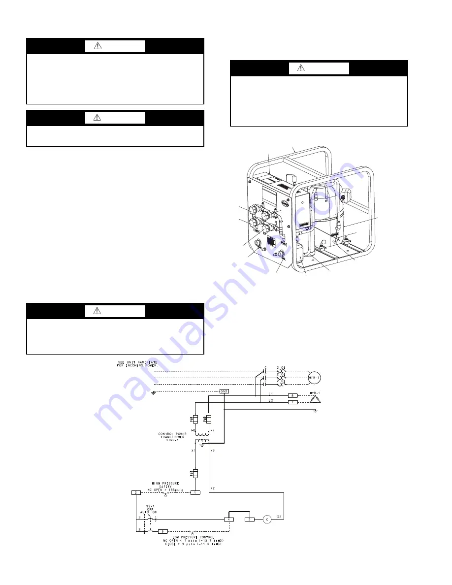
(Fig. 47) —
Oil should be visible in the pumpout unit com-
pressor sight glass under all operating conditions and during
shutdown. If oil is low, add oil as described under Optional
Pumpout System Maintenance section, page 98. The pumpout
unit control wiring schematic is detailed in Fig. 48.
TO READ REFRIGERANT PRESSURES (during pumpout
or leak testing):
1. The ICVC display on the chiller control panel is suitable
for determining refrigerant-side pressures and low (soft)
vacuum. To assure the desired range and accuracy when
measuring evacuation and dehydration, use a quality
vacuum indicator or manometer. This can be placed on
the Schrader connections on each vessel (Fig. 2 and 3) by
removing the pressure transducer.
2. To determine pumpout storage tank pressure, a 30 in. Hg
vacuum -0-400 psi (-101-0-2769 kPa) gage is attached to
the storage tank.
3. Refer to Fig. 43 and 44 for valve locations and numbers.
POSITIVE PRESSURE CHILLERS WITH STORAGE
TANKS — In the Valve/Condition tables that accompany these
instructions, the letter “C” indicates a closed valve. Figures 43
and 44 show the locations of the valves.
DANGER
During transfer of refrigerant into and out of the optional
storage tank, carefully monitor the storage tank level gage.
Do not fill the tank more than 90% of capacity to allow for
refrigerant expansion. Overfilling may result in damage to
the tank or the release of refrigerant which will result in
personal injury or death.
CAUTION
Do not mix refrigerants from chillers that use different
compressor oils. Compressor damage can result.
CAUTION
Transfer, addition, or removal of refrigerant in spring-
isolated chillers may place severe stress on external piping
if springs have not been blocked in both up and down
directions.
CAUTION
Always run chiller cooler and condenser water pumps and
always charge or transfer refrigerant as a gas when chiller
vessel pressure is less than 35 psig (241 kPa). Below these
pressures, liquid refrigerant flashes into gas, resulting in
extremely low temperatures in the cooler/condenser tubes
and possibly causing tube freeze-up.
COMPRESSOR
OIL
SEPARATOR
CONDENSER
LEAVING
WATER
ENTERING
WATER
VALVE
5
VALVE
4
VALVE
2
CONTROL
PANEL
FRAME
ASSEMBLY
OIL
HEATER
VALVE
3
OIL FILL
FITTING
Fig. 47 — Pumpout Unit
a23-1546
LEGEND
C
— Contactor
FU
— Fuse
GND — Ground
HTR
— Heater
MTR — Motor
NC
— Normally Closed
OL
— Overload
SS
— Selector Switch
Fig. 48 — Pumpout Unit Wiring Schematic
a19-2437
Содержание AquaEdge 19XR series
Страница 69: ...69 Fig 33 19XR Leak Test Procedures a19 1625 ...
Страница 150: ...150 Fig 62 PIC II Control Panel Wiring Schematic Frame 2 3 4 and E Compressors without Split Ring Diffuser a19 1870 ...
Страница 152: ...152 a19 1871 Fig 63 PIC II Control Panel Wiring Schematic Frame 4 and 5 Compressors with Split Ring Diffuser ...
Страница 154: ...154 Fig 64 Benshaw Inc Wye Delta Unit Mounted Starter Wiring Schematic Low Voltage a19 1873 ...
Страница 161: ...161 Fig 69 Typical Low Voltage Variable Frequency Drive VFD Wiring Schematic 575 v ...
Страница 162: ...162 Fig 69 Typical Low Voltage Variable Frequency Drive VFD Wiring Schematic 575 v cont ...
Страница 163: ...163 Fig 69 Typical Low Voltage Variable Frequency Drive VFD Wiring Schematic 575 v cont a19 1880 ...
Страница 176: ...176 CONTINUED ON NEXT PAGE Fig 71 Typical Medium Voltage Variable Frequency Drive VFD Wiring Schematic cont a19 2064 ...
Страница 186: ...186 APPENDIX B LEAD LAG WIRING 19XR Lead Lag Schematic Series Cooler Flow a19 1655 ...
Страница 187: ...187 APPENDIX B LEAD LAG WIRING cont 19XR Lead Lag Schematic Parallel Cooler Flow a19 1717 ...