


58
point has moved. This is used to determine the size of the speed
boost to the VFD.
NOTE: If upon ramp-up, a chiller with VFD tends to go to full
speed before guide vanes open fully, it is an indication that the
lift at low load is excessive, and the operating point moved
directly into the surge prevention region. In this case, investi-
gate the ability of the condenser cooling means (e.g., cooling
tower) to provide cooling water in accordance with the design
load/entering condenser water temperature schedule.
A surge condition occurs when the lift becomes so high the
gas flow across the impeller reverses. This condition can even-
tually cause chiller damage. When enabled, the Surge Preven-
tion Algorithm will adjust either the inlet guide vane (IGV)
position or compressor speed to maintain the compressor at a
safe distance from surge while maintaining machine efficiency.
If the surge condition degrades then the algorithm will move
aggressively away from surge. This condition can be identified
when the
SURGE/HGBP ACTIVE?
on the HEAT_EX display
screen displays a YES.
When in Surge Prevention mode, with a command to in-
crease capacity, the VFD speed will increase until maximum
VFD speed is reached. At
VFD MAXIMUM SPEED
, when Ca-
pacity still needs to increase, the IGV’s open. When in Surge
Prevention mode and with a command to decrease capacity
only the IGVs will close, the VFD speed will not decrease.
Surge Protection (VFD Chiller) —
The PIC II mon-
itors surge, which results in a fluctuation on the compressor
motor amperage. Each time the fluctuation in amperage ex-
ceeds an operator-specified limit (SURGE DELTA % AMPS)
plus a load correction factor, both SURGE COUNTS are incre-
mented by one and the VFD will increase in speed provided
that it is not already operating at VFD MAXIMUM SPEED or
that the VFD TARGET SPEED is forced. If the VFD cannot
increase in speed because the VFD is already at maximum
speed of the target speed is forced then the SURGE PROTEC-
TION COUNTS are also incremented by one. If more than 4
SURGE PROTECTION COUNTS occur within an operator-
specified time (SURGE TIME PERIOD) and the ACTUAL
VFD SPEED is greater than 90% then the PIC II declares an
Excessive Compressor Surge Alarm (238) and the chiller is
shut down. If more than four SURGE PROTECTION
COUNTS occur within the SURGE TIME PERIOD and the
ACTUAL VFD SPEED is less than 90% then the chiller is shut
down on a Excessive Compressor Surge / Low Speed Alarm
(236). Both SURGE COUNTS and SURGE PROTECTION
COUNTS are decreased by one if no surges occur within the
SURGE TIME PERIOD.
On chillers with VFDs, if a SURGE COUNT is registered
and the ACTUAL VFD SPEED is less than the VFD MAXI-
MUM SPEED then the TARGET VFD SPEED will be in-
creased by the amount configured in the VFD INCREASE
STEP parameter. The VFD will not decrease in speed if
SURGE COUNTS is greater than zero.
The threshold at which a current fluctuation is interpreted as
a surge can be adjusted from the OPTIONS screen. The por-
tion of the surge threshold attributable to current fluctuations
can be changed by scrolling to the SURGE DELTA % AMPS
parameter and adjusting it with the INCREASE or DE-
CREASE softkeys. The default setting is 10 %. The SURGE
TIME PERIOD can be adjusted from the OPTIONS screen.
Scroll to the SURGE TIME PERIOD parameter and use the
INCREASE or DECREASE softkey to adjust the surge count
time interval. The default setting is 8 minutes.
SURGE PROTECTION COUNTS are displayed in the
COMPRESS screen. Both SURGE PROTECTION COUNTS
and SURGE COUNTS are displayed in the SURGPREV
screen.
VFD Start-Up Speed Control —
Immediately accel-
erating to a high VFD speed improves the ability of the com-
pressor to compensate for some start-up environments that ex-
ceed condenser water design conditions. The 19XRV chillers
initially accelerate to high VFD speed and then gradually slow
the compressor, if possible, while adjusting the guide vane po-
sition until a stable operating point with improved chiller effi-
ciency is attained.
Following a start command, the PIC II controls internally
set the VFD TARGET SPEED to the smaller of the VFD
MAXIMUM SPEED or the VFD START SPEED. Provided
that the chiller has sufficient capacity, the VFD will continue to
run at the startup speed during Ramp Loading until the chilled
water temperature falls within the CHILLED WATER DEAD-
BAND surrounding the Setpoint. RAMP LOADING AC-
TIVE in the SURGPREV screen will indicate YES during
Ramp Loading. The GUIDE VANE DELTA will be equal to
zero when the chilled water temperature is in the CHILLED
WATER DEADBAND. The VFD speed will then be ramped
down at one half of the VFD GAIN rate until, surge conditions
are encountered, the VFD MINIMUM SPEED is reached, the
ACTUAL GUIDE VANE POS reaches the GUIDE VANE
TRAVEL LIMIT, or the TARGET VFD SPEED is forced.
VFD RAMPDOWN ACTIVE in the SURGPREV screen will
indicate YES during the rampdown process. The VFD speed
will be regulated by standard capacity control and surge pre-
vention algorithms at the conclusion of the rampdown process.
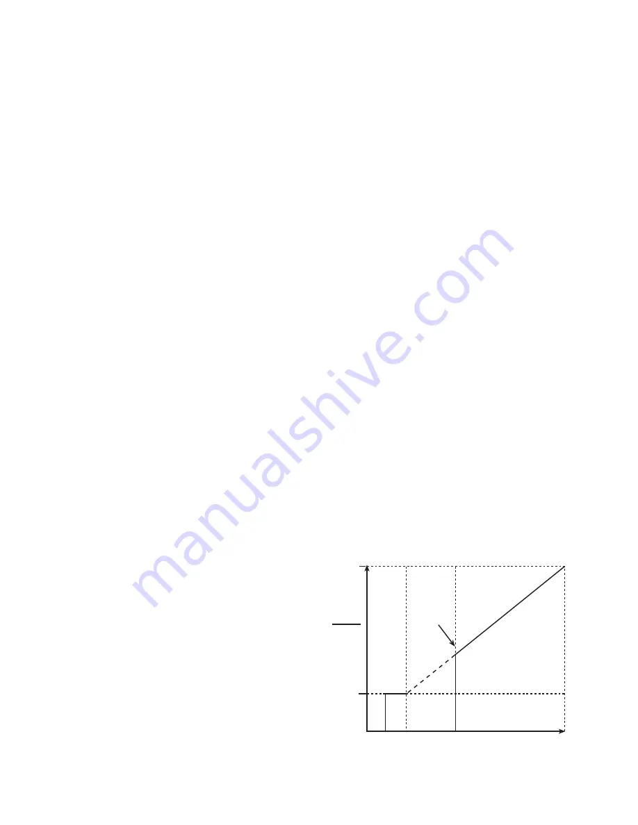
Head Pressure Reference Output (See
Fig. 28) —
The PIC II control outputs a 4 to 20 mA signal
for the configurable Delta P (CONDENSER PRESSURE mi-
nus EVAPORATOR PRESSURE) reference curve shown in
Fig. 28. An output is available on the ISM module [Terminal
J8-3 (+), J8-4 (–) labeled spare]. The
DELTA P AT 100%
(chiller at maximum load condition default at 50 psi
[344 kPa]),
DELTA P AT 0%
(chiller at minimum load condi-
tion default at 25 psi [172.4 kPa]) and
MINIMUM OUTPUT
points are configurable in the EQUIPMENT SERVICE-OP-
TIONS table. When configuring this output ensure that mini-
mum requirements for oil pressure and proper condenser
FLASC orifice performance are maintained.
The output may be useful as a reference signal to control a
tower bypass valve, tower speed control, condenser pump
speed control, etc. Note that it is up to the site design engineer-
ing agent to integrate this analog output with any external sys-
tem device(s) to produce the desired effect. Carrier does not
make any claim that this output is
directly
usable to control any
specific piece of equipment (that is, without further control ele-
ments or signal conditioning), although it may be.
MINIMUM
REFERENCE
OUTPUT
DELTA P
AT 100%
DELTA P
AT 0%
DELTA P
0 mA 2 mA 4 mA
(0%)
20 mA
(100%)
4 T0 20 mA OUTPUT
Fig. 28 — Head Pressure Reference Output
(Minimum Set Above 4 mA)
Содержание AquaEdge 19XR series
Страница 69: ...69 Fig 33 19XR Leak Test Procedures a19 1625 ...
Страница 150: ...150 Fig 62 PIC II Control Panel Wiring Schematic Frame 2 3 4 and E Compressors without Split Ring Diffuser a19 1870 ...
Страница 152: ...152 a19 1871 Fig 63 PIC II Control Panel Wiring Schematic Frame 4 and 5 Compressors with Split Ring Diffuser ...
Страница 154: ...154 Fig 64 Benshaw Inc Wye Delta Unit Mounted Starter Wiring Schematic Low Voltage a19 1873 ...
Страница 161: ...161 Fig 69 Typical Low Voltage Variable Frequency Drive VFD Wiring Schematic 575 v ...
Страница 162: ...162 Fig 69 Typical Low Voltage Variable Frequency Drive VFD Wiring Schematic 575 v cont ...
Страница 163: ...163 Fig 69 Typical Low Voltage Variable Frequency Drive VFD Wiring Schematic 575 v cont a19 1880 ...
Страница 176: ...176 CONTINUED ON NEXT PAGE Fig 71 Typical Medium Voltage Variable Frequency Drive VFD Wiring Schematic cont a19 2064 ...
Страница 186: ...186 APPENDIX B LEAD LAG WIRING 19XR Lead Lag Schematic Series Cooler Flow a19 1655 ...
Страница 187: ...187 APPENDIX B LEAD LAG WIRING cont 19XR Lead Lag Schematic Parallel Cooler Flow a19 1717 ...