


117
Control Algorithms Checkout Procedure —
One
of the tables on the ICVC SERVICE menu is CONTROL
ALGORITHM STATUS. The maintenance screens may be
viewed from the CONTROL ALGORITHM STATUS table to
see how a particular control algorithm is operating.
These maintenance screens are very useful in helping to de-
termine how the control temperature is calculated and guide
vane positioned and for observing the reactions from load
changes, control point overrides, hot gas bypass, surge preven-
tion, etc. The tables are:
Control Test —
The Control Test feature can check all the
thermistor temperature sensors, pressure transducers, pumps
and their associated flow devices, the guide vane actuator, and
other control outputs such as tower fans, shunt trip relay, oil
heater, alarm relay, and hot gas bypass. The tests can help to
determine whether a switch is defective or a pump relay is not
operating, as well as other useful troubleshooting issues.
During pumpdown operations, the pumps are energized to pre-
vent freeze-up and the vessel pressures and temperatures are
displayed. The Pumpdown/Lockout feature prevents compres-
sor start-up when there is no refrigerant in the chiller or if the
vessels are isolated. The Terminate Lockout feature ends the
Pumpdown/Lockout after the pumpdown procedure is reversed
and refrigerant is added.
Control Modules
The ICVC and CCM modules perform continuous diagnos-
tic evaluations of the hardware to determine its condition.
Proper operation of all modules is indicated by LEDs (light-
emitting diodes) located on the circuit board of the ICVC and
CCM.
There is one green and one red LED located on the CCM
and ICVC boards.
RED LED (LABELED AS STAT) — If the red LED:
• blinks continuously at a 2-second interval, the module is
operating properly
• is lit continuously, there is a problem that requires
replacing the module
• is off continuously, the power should be checked
• blinks 3 times per second, a software error has been dis-
covered and the module must be replaced
If there is no input power, check the fuses and circuit break-
er. If the fuse is good, check for a shorted secondary of the
transformer or, if power is present to the module, replace the
module.
GREEN LED (LABELED AS COM) — These LEDs indi-
cate the communication status between different parts of the
controller and the network modules and should blink continu-
ously.
Notes on Module Operation
1. The chiller operator monitors and modifies configura-
tions in the microprocessor by using the 4 softkeys and
the ICVC. Communications between the ICVC and the
CCM is accomplished through the SIO (Sensor Input/
Output) bus, which is a phone cable.
2. If a green LED is on continuously, check the communica-
tion wiring. If a green LED is off, check the red LED op-
eration. If the red LED is normal, check the module ad-
dress switches (SW1) (Fig. 54 and 55). Confirm all
switches are in OFF position.
All system operating intelligence resides in the ICVC.
Outputs are controlled by the CCM as well.
3. Power is supplied to the modules within the control panel
via 24-vac power sources.
The transformers are located within the power panels.
In the power panel, T1 supplies power to the compressor
oil heater, oil pump, and optional hot gas bypass, and T2
supplies power to both the ICVC and CCM.
T3 provides 24-v power to the optional modules.
Power is connected to Plug J1 on each module.
Chiller Control Module (CCM) (Fig. 55)
INPUTS — Each input channel has 2 or 3 terminals. Refer to
individual chiller wiring diagrams for the correct terminal
numbers for your application.
OUTPUTS — Output is 24 vac. There are 2 terminals per out-
put. Refer to the chiller wiring diagram for your specific appli-
cation for the correct terminal numbers.
Integrated Starter Module (Fig. 56)
INPUTS — Inputs on strips J3 through J6 are analog inputs
and J2 is discrete (on/off) input. The specific application of the
chiller determines which terminals are used. Refer to the indi-
vidual chiller wiring diagram for the correct terminal numbers
for your application.
OUTPUTS — Outputs are rated for 115-277 vac and wired to
strip J9. There are 2 terminals per output.
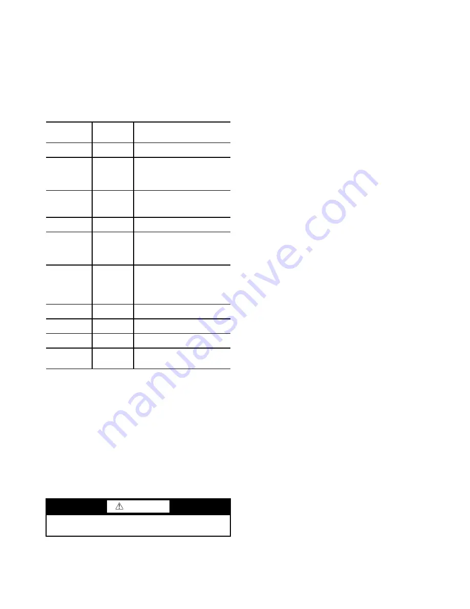
CAPACITY
Capacity
Control
This table shows all values used
to calculate the chilled water/brine
control point.
OVERRIDE
Override
Status
Details of all chilled water control
override values.
SURG_PREV
Surge/
HGBP
Status
The surge and hot gas bypass
control algorithm status is viewed
from this screen. All
values dealing with this control
are displayed.
HEAT_EX
Heat
Exchanger
Points
Status
All sensor inputs and calculated
values related to the heat
Exchangers. Also some of the
surge control points are shown.
LL_MAINT
LEAD/LAG
Status
Indicates LEAD/LAG operation
status.
OCCDEFCM
Time
Schedules
Status
The Local and CCN occupied
schedules are displayed here to
help the operator quickly deter-
mine whether the schedule is in
the “occupied” mode or not.
WSMDEFME
Water
System
Manager
Status
The water system manager is a
CCN module that can turn on the
chiller and change the chilled
water control point. This screen
indicates the status of this sys-
tem.
ISM_HIST
ISM Alarm
History
Displays ISM values at last fault.
LOADSHED
Loadshed
Status
Displays Loadshed (Demand
Limit) status.
CUR_ALARM
Current
Alarm Status
Displays current chiller alarms.
SURGPREV
Surge Pre-
vention Sta-
tus
Displays all information used or
supplied by the surge prevention
algorithm.
CAUTION
Turn controller power off before servicing controls. This
ensures safety and prevents damage to the controller.
Содержание AquaEdge 19XR series
Страница 69: ...69 Fig 33 19XR Leak Test Procedures a19 1625 ...
Страница 150: ...150 Fig 62 PIC II Control Panel Wiring Schematic Frame 2 3 4 and E Compressors without Split Ring Diffuser a19 1870 ...
Страница 152: ...152 a19 1871 Fig 63 PIC II Control Panel Wiring Schematic Frame 4 and 5 Compressors with Split Ring Diffuser ...
Страница 154: ...154 Fig 64 Benshaw Inc Wye Delta Unit Mounted Starter Wiring Schematic Low Voltage a19 1873 ...
Страница 161: ...161 Fig 69 Typical Low Voltage Variable Frequency Drive VFD Wiring Schematic 575 v ...
Страница 162: ...162 Fig 69 Typical Low Voltage Variable Frequency Drive VFD Wiring Schematic 575 v cont ...
Страница 163: ...163 Fig 69 Typical Low Voltage Variable Frequency Drive VFD Wiring Schematic 575 v cont a19 1880 ...
Страница 176: ...176 CONTINUED ON NEXT PAGE Fig 71 Typical Medium Voltage Variable Frequency Drive VFD Wiring Schematic cont a19 2064 ...
Страница 186: ...186 APPENDIX B LEAD LAG WIRING 19XR Lead Lag Schematic Series Cooler Flow a19 1655 ...
Страница 187: ...187 APPENDIX B LEAD LAG WIRING cont 19XR Lead Lag Schematic Parallel Cooler Flow a19 1717 ...