S T E P 1 0
S T E P 1 0 – S e t U p M a c h i n e ‑ C o n t r o l S o f t w a r e
60
docs.carbide3d.com
61
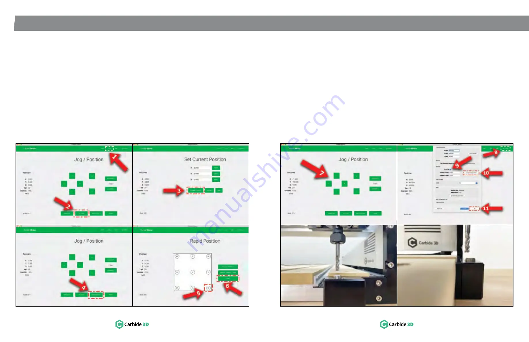
10.6 Set Up the BitSetter
Now you’re ready to set up the BitSetter. First you
will need to position the router above the BitSetter
(
see
Figs. 10-5 and 10-6)
:
1. Click
Jog
in the top menu bar.
2. Click the
Set Zero button
.
3. Click the
Clear All Offsets button
and then
click
Done
.
4. On the
Jog screen
, click the
Rapid Position
button
.
5. Click
SE button
to move the router to the
front-right corner of the machine.
6. Once machine is in position, click
Done
.
7. On the
Jog screen
, use the
Y+ / Y-
and
X+ / X-
buttons
(or the arrows on your keyboard) to
jog the gantry so the router is directly above
the BitSetter.
See
Fig. 10-6
.
Figure 10-5
Next, you will need to configure the permanent
position of the BitSetter in Carbide Motion (
see
Fig. 10-6)
:
8. Click
Settings
in the top menu bar.
9. In the
BitSetter section
, select the
Enabled
checkbox
.
10. With your router still positioned directly above
the BitSetter, click the
Use Current Location
button
. This will permanently save the X/Y
location of your router.
11. Click
Ok
to save and close.
10.7 Set the Post Processor
in Carbide Create
Carbide Create must have the post processor set
to Carbide 3D Shapeoko for the BitSetter to work.
To set the post processor:
1. Go to
Edit
in the top menu bar.
2. Choose
Select Post Processor
.
3. Choose
Carbide 3D Shapeoko
.
4. In the
Output Units dropdown list
, select
Inch
or
Metric
.
5. Click
OK
to save and close.
Figure 10.6
Содержание Shapeoko PRO
Страница 1: ...Shapeoko PRO ASSEMBLY GUIDE...


