S T E P 9
S T E P 9 – C o n t r o l l e r
52
docs.carbide3d.com
53
9.1 Install Controller
1. Screw the two (2) controller standoffs into
the second and fifth threaded holes from the
REAR of the Y-Right rail. Hand tighten.
2. Adjust the length of the two cables exiting the
rail between the standoffs to about 8 inches.
3. Position the controller over the standoffs.
a. Power and USB to the back.
See
Fig. 9-2
.
b. PCB will be upside down.
4. Use a 4mm hex key and two (2) M6×12mm
BHCS to secure the controller to the standoffs.
Fully tighten.
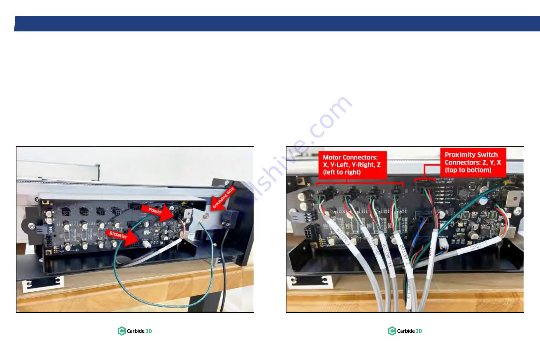
Figure 9-2
Figure 9-3
9.2 Connect Controller Cables
1. Use a 4mm hex key and one (1) M6×10mm FHS
(found in the Extra Hardware Bag) to secure
the green grounding wire to the first threaded
hole from the rear of the rail.
See
Fig. 9-2
.
2. Plug the 4-pin male power cable into the
4-pin female connector at the top-right of the
controller labeled “Pwr_conn”.
3. Plug the 3-pin female BitSetter cable into the
3-pin male connector at the bottom of the
controller labeled “BitSetter”.
4. Plug the three 8-pin male proximity switch
cables into the 8-pin female connectors down
the center of the controller labeled “Z”, “Y”,
“X”.
See
Fig. 9-3
.
5. Plug the four 4-pin male stepper motor cables
into the 4-pin female connectors at the top-left
labeled “X”, “Y2”, “Y1”, “Z”.
See
Fig. 9-3
.
a. Y-RIGHT motor cable into “Y1” connector.
b. Y-LEFT motor cable into “Y2” connector.
PRO TIP:
Keep an eye on the gantry when you
home the machine for the first time. The gantry
should home to the back-right corner. If your
gantry moves forward during homing, you may
need to swap the Y-Left and Y-Right motor cables
at the controller.
6. Use the four (4) thumbscrews to attach the
controller cover.
a. Direct all of the cables into the notch at the
bottom.
Содержание Shapeoko PRO
Страница 1: ...Shapeoko PRO ASSEMBLY GUIDE...


