Control Overview
20 APOLLO
Digital Broadcast Production Console
SURFACE CONTROL OVERVIEW
Apollo works the way you want to.
A variety of operating modes and
different ways to display information
ensure that every operator will feel at
home behind the console.
There are a range of different panels
available that make up the Apollo surface.
These are detailed in the ‘Surface Panel
Overview’ section of this document. It is
first important to understand the different
control types which make up these panels.
The main control types on the surface are
as follows:
Rotary controls
The rotary controls on the surface will
change colour to reflect the type of
control they are currently assigned to. For
example, when assigned to an Aux control
they would be coloured green.
Buttons
The small square and triangular buttons,
like the rotary controls, change colour
when active to reflect the currently
assigned control. Where there are
buttons that relate to the same control
as displayed on a control cell display,
the buttons will be used for control. The
control cell displays are not touch sensitive
when a physical button is present.
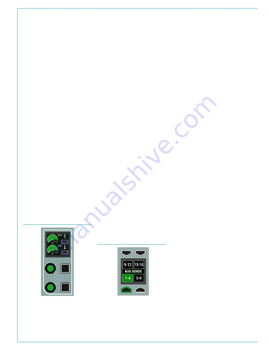
Control cell
The two interface elements described
above are combined with a display to
make up control cells. One of these cells
is shown in Fig 1.
The upper rotary control and button
control the parameters shown in the
upper half of the control cell display.
The lower rotary control and button
control the parameter shown in the
lower area of the control cell display.
Controls that are not active (e.g pan
controls when assigned to a surround bus)
are hidden; the rotary controls, buttons
and control cell display sections will not
be lit.
Button cell
In a button cell, as shown in Fig 2, the
buttons map directly to the nearest control
cell display. Each graphic display is split
into up to four functions. Buttons above
and below point to the functions on the
displays that they control. Some functions
are shown the full width of the display. In
these cases, pressing either of the two
buttons will activate the function.
A strip across the centre of a button cell
is sometimes used as a label. Labels
sometimes span across more than one
display and sometimes a cell may have a
label but no associated button functions.
Strip
A Strip is a collection of controls that are
specific to each fader on the surface. For
example, each fader control cell always
contains controls that affect the fader
directly below it. The control cells and
TFT on the wild assign panel may also be
arranged in this way dependent on the
wild assign panel mode.
Rows
Certain horizontal sets of controls are
used together to group similar controls.
These are known as
rows
. See Fig 3.
Each row on the surface has a name, such
as ‘Functions row’ or ‘Modes row’. The
rows are identified on the next page.
The Layers row and Modes row always
span the width of the panel and contain
controls that do not relate directly to a
specific fader.
TFT touchscreen
Various control parameters in the
different panel modes are changed using
buttons located on the TFT touchscreen
of the Wild Assign panel.
If a touchscreen is found to be inaccurate,
it can be calibrated - Press the Tools
button in the right-hand button-cell of the
modes row. This replaces the fader layer
select buttons with setup functions. Press
the Misc button, then select CAL TFT
from the row of button cells above. From
a normal seating position, press the TFT
touchscreen in the centre of the targets
presented. Once complete, change the
panel mode to refresh the display.
FIG 1 - CONTROL CELL
FIG 2 - BUTTON CELL
Содержание Apollo
Страница 7: ...calrec com Putting Sound in the Picture APOLLO INFORMATION...
Страница 11: ...calrec com Putting Sound in the Picture APOLLO INTRODUCTION...
Страница 16: ...16 APOLLO Digital Broadcast Production Console Introduction...
Страница 17: ...calrec com Putting Sound in the Picture APOLLO CONTROL OVERVIEW...
Страница 21: ...CALREC Putting Sound in the Picture 21 FIG 3 ROWS...
Страница 36: ...Control Overview 36 APOLLO Digital Broadcast Production Console FIG 3 EXAMPLE LAYOUTS...
Страница 40: ...40 APOLLO Digital Broadcast Production Console...
Страница 41: ...calrec com Putting Sound in the Picture APOLLO CONTROL PANEL MODES...
Страница 49: ...CALREC Putting Sound in the Picture 49 WILDABLE CONTROLS...
Страница 52: ...52 APOLLO Digital Broadcast Production Console...
Страница 53: ...calrec com Putting Sound in the Picture APOLLO GETTING SIGNALS INTO APOLLO...
Страница 82: ...82 APOLLO Digital Broadcast Production Console Getting Signals into Apollo...
Страница 83: ...calrec com Putting Sound in the Picture APOLLO PROCESSING AUDIO...
Страница 110: ...110 APOLLO Digital Broadcast Production Console...
Страница 111: ...calrec com Putting Sound in the Picture APOLLO ROUTING AUDIO...
Страница 128: ...128 APOLLO Digital Broadcast Production Console...
Страница 129: ...calrec com Putting Sound in the Picture APOLLO PASSING SIGNALS OUT OF APOLLO...
Страница 137: ...calrec com Putting Sound in the Picture APOLLO MONITORING...
Страница 152: ...152 APOLLO Digital Broadcast Production Console...
Страница 153: ...calrec com Putting Sound in the Picture APOLLO COMMUNICATIONS...
Страница 158: ...158 APOLLO Digital Broadcast Production Console...
Страница 159: ...calrec com Putting Sound in the Picture APOLLO METERING...
Страница 168: ...168 APOLLO Digital Broadcast Production Console...
Страница 169: ...calrec com Putting Sound in the Picture APOLLO SHOWS MEMORIES AND PRESETS...
Страница 183: ...calrec com Putting Sound in the Picture APOLLO CONSOLE FACILITIES...
Страница 188: ...188 APOLLO Digital Broadcast Production Console...
Страница 189: ...calrec com Putting Sound in the Picture APOLLO EXTERNAL INTERFACING...
Страница 199: ...calrec com Putting Sound in the Picture APOLLO SYSTEM STATUS...
Страница 202: ...202 APOLLO Digital Broadcast Production Console...
Страница 203: ...calrec com Putting Sound in the Picture APOLLO GLOSSARY OF TERMINOLOGY...
Страница 209: ...calrec com Putting Sound in the Picture APOLLO FEATURES BY SOFTWARE VERSION...


