background image

CALREC 

Putting Sound in the Picture


131

OUTPUT PORT PROTECTION

Output port protection is a system 
that notifies operators when they 
are attempting to patch to outputs 
that are already in use by other 
people elsewhere on the network, 
and provides information to assist in 
deciding whether to go ahead with 
each patching decision.

All output destinations can be available to 
all consoles on a Hydra2 network if they 
have been granted access within H2O, 
but only one audio feed can be routed to 
each individual output at any one time. 
When an output is in use, it is ‘protected’ 
from over-patching by other users on the 
network. 

You can always overpatch your own 
patches.  They are only protected from 
being overpatched by someone else.

Patching to Protected Outputs

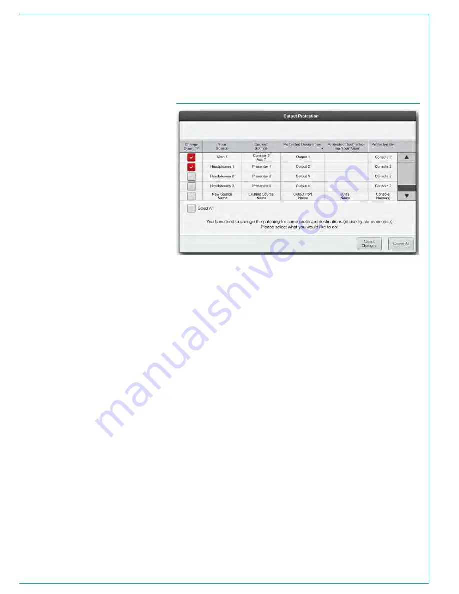
When an operator patches to a protected 
output, either by console patching or by 
loading shows, user memory or alias files, 
a pop-up appears on the main application 
screen containing a table of information to 
assist in choosing whether to go through 
with the new patching or to keep the 
current settings.  See Fig 1.

The check boxes down the left hand side 
of the table are used to select each patch 
change individually.  The ‘Select All’ check 
box selects and deselects all patching 
changes as a whole.

On clicking ‘Accept Changes’, changes 
which are checked in the pop-up, plus 
any changes which are not displayed due 
to them having no effect on protected 
outputs are all made and the pop-up 
closes.  

On clicking CANCEL ALL, all changes 
that affect protected outputs are rejected 
but all changes which do not affect 
protected outputs are made and the pop-
up closes. 

If a user memory is loaded from the 
surface’s memories panel area when in 
monitor mode, a simplified version of the 
pop-up is also displayed on the surface 
allowing the operator to accept or cancel 
all changes, providing output protection 
notification on the surface, without 
reliance on the system PC.

Always ensure patching changes are 
correct before accepting them as 
you may affect other users on the 
network.

Output Protection differs from local 
lock of output ports.  Local lock is a 
manual process which locks an output 
for all operators of that console, whereas 
output protection is an automatic 
process designed to prevent accidental 
over-patching during operation, whilst   
retaining a smooth workflow.

As detailed in the Input Port Protection 
section of this manual, when loading 
shows, user memory or Alias files it is 
likely that both protected outputs and 
shared inputs will be affected by the 
memory load.  In this case the pop-up 
will have two stages - Input Sharing and 
Output Protection.

FIG 1 - OUTPUT PROTECTION POP-UP

Содержание Apollo

Страница 1: ...calrec com Putting Sound in the Picture APOLLO OPERATOR MANUAL Digital Broadcast Production Console V8 1...

Страница 2: ...ernational usage Calrec Audio Ltd reserve the right to change specifications without notice E O E The established policy of Calrec Audio Ltd is to seek improvements to the design specifications and ma...

Страница 3: ...ng lists 56 Sets 56 Adding ports to sets 57 Allocating Signal Paths to Faders 58 Assigning channels to faders 58 Assigning buses to faders 58 Assigning auxs and tracks to faders in the Tools menu 59 I...

Страница 4: ...rrogation 105 Masters and slaves on the same fader 105 Fader level indicator 105 Nulling indicators 105 Preserving balance of slaves at low levels 105 5 1 Surround channels 105 VCA group protection 10...

Страница 5: ...controls 140 Loudspeaker cut buttons 140 Monitoring for multiple users 140 Monitoring at different sample rates 140 Dedicated Monitor Controls 141 AFL PFL and Output Listen 142 AFL 142 PFL 142 Output...

Страница 6: ...unts 186 Exiting Technician Mode 186 Synchronisation Sources 187 Synchronisation at different sample rates 187 External Interfacing 189 GPIO 190 Assigning GPIs 190 GPI functions 190 Mon Spill Panel Cu...

Страница 7: ...calrec com Putting Sound in the Picture APOLLO INFORMATION...

Страница 8: ...ly static sensitive parts are exposed In order to protect these devices from damage and to protect your warranty please observe static handling procedures for example use an appropriately grounded ant...

Страница 9: ...Do not allow ventilation slots to be blocked Do not leave the equipment powered up with the dust cover fitted Cleaning For cleaning the front panels of the equipment we recommend using a soft anti st...

Страница 10: ...oviding export documentation for the return of faulty parts On site commissioning visits On site service and health check visits Emergency engineer visits On site on air support for complete peace of...

Страница 11: ...calrec com Putting Sound in the Picture APOLLO INTRODUCTION...

Страница 12: ...ty Commitment Calrec has a world wide customer base which includes many of the world s most prestigious broadcasters and covers the highest profile events By consistently focusing upon purely broadcas...

Страница 13: ...sends per path from pool of 256 mono legs Insert Send Returns Pool of 256 mono legs Pool of 128 mono legs Input Delay Up to 2 73s per input from pool of 256 mono legs Up to 2 73s per input from pool o...

Страница 14: ...re stored and recalled at show level The System Settings area contains the remaining functions that are stored at system level and do not change with shows The table in Fig 1 shows the Old and New nam...

Страница 15: ...that is at a different sample rate to the desk Note these patches can be made in H2O and by SW P 08 and will work if patched there System Status messages are produced for I O boxes HPB that are in the...

Страница 16: ...16 APOLLO Digital Broadcast Production Console Introduction...

Страница 17: ...calrec com Putting Sound in the Picture APOLLO CONTROL OVERVIEW...

Страница 18: ...main menu which contains buttons for each of the main sections of the application When this document instructs you to go to the MEM section for example it is the equivalent of saying touch the MEM bu...

Страница 19: ...release without changing position See Fig 1 Multiple touches Hold and Touch In some cases it is necessary to combine touch controls to achieve the desired result One control will normally be held whi...

Страница 20: ...In a button cell as shown in Fig 2 the buttons map directly to the nearest control cell display Each graphic display is split into up to four functions Buttons above and below point to the functions...

Страница 21: ...CALREC Putting Sound in the Picture 21 FIG 3 ROWS...

Страница 22: ...on Console Fader Panel Each fader panel consists of 8 fader strips at a fader pitch of 30 mm Each fader strip contains an A B assign section a button cell and a control cell A blank fader panel is sho...

Страница 23: ...5 0 10 0 20 10 10 START ON 0 4 8 12 16 20 24 42 E C 60 DYN 2 DYN 1 O P 1 PATH 4 8 12 16 20 24 42 E C 60 DYN 2 DYN 1 O P 1 PATH 4 8 12 16 20 24 42 E C 60 DYN 2 DYN 1 O P 1 PATH 4 8 12 16 20 24 42 E C...

Страница 24: ...e Layers row is used for layer switching and accessing certain other panel functions The Functions row changes between displaying controls relevant to each fader as shown in the previous figure or a r...

Страница 25: ...the panel is operating in The panel could be in Assign Outputs Monitor Strips or Wilds mode Assign mode makes the panel function as an assignable panel In much the same way as previous Calrec assignab...

Страница 26: ...Control Overview 26 APOLLO Digital Broadcast Production Console Each type of control on the wild assign panel is detailed in Fig 5 FIG 5 WILD ASSIGN PANEL CONTROLS...

Страница 27: ...Assign Outputs or Monitor mode this functions as a panel wide row working with various controls in the control cells and mini TFTs above In Strips or Wilds mode the panel is divided up into eight ver...

Страница 28: ...erview 28 APOLLO Digital Broadcast Production Console TFT Panel This is primarily used to display metering information and is not touch controlled An example meter layout is shown in Fig 7 FIG 7 TFT M...

Страница 29: ...controls and a set of A B assign keys either side of an control cell display The panel also contains a subset of the main monitoring controls including the large CR Monitor level knob small LS trim a...

Страница 30: ...see Fig 9 can act as either a spill controller downmix controller or a main output controller accessed via the four 60mm faders Instead of monitor controls the lower green area of the panel is dedica...

Страница 31: ...and also a USB connector which allows you to plug in a USB memory stick which can be used to load and store console configurations from the configuration PC in the body of the console At the bottom of...

Страница 32: ...Both rows are touch sensitive as on the standard fader panel The controls in the Tools and Layer Tools functions of the standard fader panel are also accessible on the dual fader panel They are acces...

Страница 33: ...ontrols relate to the active path is determined by which assign button A or B is selected for each fader The active path for each fader can be changed by pressing the relevant assign button The path l...

Страница 34: ...Console Custom Metering Panel This panel provides the customer with an area to mount moving coil PPM VU style meters and or Vectorscope displays such as the DK MSD600M Fig 13 or the RTW 10800 range Fi...

Страница 35: ...ace layout has been altered and the user needs to quickly get back to a known and familiar state It is also useful to be able to switch between two operational concepts easily The user could switch be...

Страница 36: ...Control Overview 36 APOLLO Digital Broadcast Production Console FIG 3 EXAMPLE LAYOUTS...

Страница 37: ...areas of the surface will display and allow control of parameters of that assigned path For example any wild assign panels in Assign mode and the surround spill panel will update to reflect values of...

Страница 38: ...hree different APFL bus sets each of which can be patched to outputs for local monitoring and the two main monitors can be configured to be interrupted by different APFL sets allowing each user to be...

Страница 39: ...tions of sources A path may appear on multiple layers simultaneously Layer Locking A path can be locked to a fader and remain on the surface regardless of the selected layer To lock a path touch the L...

Страница 40: ...40 APOLLO Digital Broadcast Production Console...

Страница 41: ...calrec com Putting Sound in the Picture APOLLO CONTROL PANEL MODES...

Страница 42: ...e stereo path width disable AutoFaders and override remote control Overview provides the essential controls you need to reach quickly If you need more detailed control change to the dedicated EQ Dynam...

Страница 43: ...panel mode allows for the currently assigned path to be routed to the various buses outputs that are available The TFT screen provides routing buttons and displays whilst the panel below provides col...

Страница 44: ...uttons if applicable for each output bus Button cells in the bottom row allow for different groups of outputs buses to be viewed in the control cells above Pressing down on a rotary control highlights...

Страница 45: ...selectors are located in the bottom row Pressing SEL on any of these makes it the focus of the right hand side of the TFT screen allowing for the source to be changed and for miscellaneous settings to...

Страница 46: ...row Selecting Wilds Any combination of Wildable path controls can be assigned to the rotary controls and buttons in the Wild assignment areas in Fig 1 In SET UP WILDS mode press the rotary control or...

Страница 47: ...elect after any successful clear operation In Setup Wilds mode select Wild rotary control or button s from the assign or fader panel The selection will flash red From another console panel select any...

Страница 48: ...s mode except the user is confined to assigning Fader Wilds Memory Isolation The Memory Isolation function includes the ability to prevent the wilds of any path from being overwritten when loading a m...

Страница 49: ...CALREC Putting Sound in the Picture 49 WILDABLE CONTROLS...

Страница 50: ...s not locked by checking the status of the MODE LOCK button also located on the Modes row The MODE LOCK button is always available even in strip type select mode allowing the user to switch between ST...

Страница 51: ...ich shows the fader number and path label This changes colour to indicate whether the A green or B yellow path is selected on the fader The currently assigned path is coloured blue Changing Strips typ...

Страница 52: ...52 APOLLO Digital Broadcast Production Console...

Страница 53: ...calrec com Putting Sound in the Picture APOLLO GETTING SIGNALS INTO APOLLO...

Страница 54: ...atch In H2O a new button labelled Sample Rate is made available selecting this opens the list of I O boxes connected to the Hydra2 Network The list shown in Fig 1 shows the sample rate set for each I...

Страница 55: ...om the Apollo system As all I O is contained in a Hydra2 network each input socket on a Hydra2 box can be termed an input port Hydra2 Patchbays Hydra2 patchbays are virtual patchbays within the Hydra2...

Страница 56: ...ls screen in the main application Fig 2 Select the Input Alloc or Output Alloc button at the left of the screen to work with input or output ports respectively The screen will show all available port...

Страница 57: ...t Select the ports that re to be stored in a set and touch the Create Set button The number of the set will appear next to the ports The order of the ports within the set can be changed by selecting a...

Страница 58: ...from the available DSP resource pool DSP resources are quoted in mono channel legs When a stereo channel is allocated 2 mono paths are used from the resource pool and 6 are used to create a 5 1 surro...

Страница 59: ...the EXEC or CNCL buttons to execute or cancel the selection respectively Layer locking faders Each fader can be locked to a chosen layer Layer locking ensures that chosen paths are always active and a...

Страница 60: ...e copied are IP1 DELAY Input 1 settings 48V input trim SRC and input delay IP2 DELAY Input 2 settings 48V input trim SRC and input delay EQ 1 4 EQ bands 1 4 EQ 5 6 EQ bands 5 6 DYN1 DYN2 PATH DELAY Pa...

Страница 61: ...the surface in the same way as the patching screen This behaviour can be toggled in the States button in the left hand side of the footer of the main application FIG 1 MAIN APPLICATION OPERATE FADER S...

Страница 62: ...able destinations menu Destination types are listed in a column down the right hand side of this menu Highlighting My Desk Inputs displays the types of DSP inputs available to patch to clicking Channe...

Страница 63: ...different sample rates Port to port patches cannot be made for I O that is at a different sample rate to the desk However they can be made in H2O and by SW P 08 providing the source and destination po...

Страница 64: ...ill also appear in the Select Sources menu Consoles can patch their DSP outputs to Hydra2 Patchbays which can in turn be patched as console sources allowing consoles to share their outputs across the...

Страница 65: ...lable on the surface In the area at the top of the touch display in Processing mode INPUT PATCHING OUTPUT PATCHING and INSERT PATCHING buttons are available depending on the type of path accessed Tapp...

Страница 66: ...This can be very useful for diagnostics It s also possible to turn off dynamic labels received via SW P 08 or when showing the sources of Hydra Patchbays see Fig 8 Custom fader labels The Label colum...

Страница 67: ...the INPUT 1 and INPUT 2 selection buttons A common use for input 2 is for backup microphones allowing them to be easily available using the same fader processing and routing as when using the primary...

Страница 68: ...n on the TFT touchscreen overrides the input of the path with tone at the frequency and level currently set When tone is applied to a channel an indicator will appear on the input controls the fader a...

Страница 69: ...ing both switches on sums the left and right portions of the signal together and outputs this on both the left and right legs With both switches in the same position either on or off you have access t...

Страница 70: ...ess Replay control buttons can be accessed by selecting TOOLS and then MISC from the Layers row On the far left of the functions row above there are two buttons associated with replay ON and SETUP Add...

Страница 71: ...To alter a protected input s Mic Gain 48v or SRC simply hold down the corresponding fader s assign button whilst making the desired change using the usual surface controls Loading Shows Memory Alias...

Страница 72: ...out the changes before being prompted to ACCEPT CHANGES again See Fig 3 Remember to ensure you know what the effect of the memory load will be before selecting ACCEPT CHANGES as this will alter the pr...

Страница 73: ...n SDI or MADI stream LED s A B C D on the front of the module itself illuminate green to show if decoder cards have been fitted in the four available slots on the module Passing signals through decode...

Страница 74: ...patched in the same way as regular I O ports To put them on input channel paths choose My Desk Inputs from the Select Destinations menu or to pass the decoded audio straight out they can also be patc...

Страница 75: ...are shown in the right hand window and can be placed as part of the alias by touching the Add Ports button Once added the ports can be given a function related name as shown in Fig 1 The commonly used...

Страница 76: ...er form of grouping that may be in use on a console Alias mic bus Alias Mic Bus allows the ports to be assigned to one or more of the console s five mic open buses so that studio speaker muting is cor...

Страница 77: ...the mode of panels or the assigned focus by selecting a different fader or output bus does not clear the tone Tone will remain until deselected or globally cleared FIG 2 OSCILLATOR CONTROLS The Oscil...

Страница 78: ...han front L R there must be a problem with routing or patching All Idents apart from BLITS can be used in conjunction with the Oscillator sweep function Selecting BLITS automatically disables the swee...

Страница 79: ...t outputs at the same level This is because tone is being applied at the final output stage With tone to line selected the signal on LoRo LtRt is NOT derived from a downmix or encoding of the surround...

Страница 80: ...rollers via SW P 08 Consoles can patch signals to their own or shared Hydra2 Patchbay inputs in the same way they patch to physical output ports Hydra2 Patchbays allow network administrators via H2O t...

Страница 81: ...changes directly affect other network users Console operators are given the ability to change the source feeding a HPB that is feeding other consoles to add increased flexibility However we advise tha...

Страница 82: ...82 APOLLO Digital Broadcast Production Console Getting Signals into Apollo...

Страница 83: ...calrec com Putting Sound in the Picture APOLLO PROCESSING AUDIO...

Страница 84: ...ction Console CHANNEL SIGNAL FLOW Fig 1 below illustrates the signal flow in an Apollo channel path showing how Inserts EQ Dynamics Path Delay and the relevant send and output points can be positioned...

Страница 85: ...ibed here in greater detail These controls would only affect the currently assigned path On Off Buttons in the left button cell switch all bands 1 4 on or off together and bands 5 and 6 on or off toge...

Страница 86: ...on is not pressed the rotary doubles as the Q control Fig 2 shows the Response Types and parameters EQ curve display The touchscreen shows a graphical representation of the current EQ curve for the as...

Страница 87: ...y and Depth and 2 bands of Dynamics sidechain EQ controls for Gain Frequency and Q Response types The TFT screen displays a graph of input level versus output level along with switchable gain reductio...

Страница 88: ...ewed by selecting SCEQ ON from the TFT screen on the left of the EQ curve or from the panel as described About Dynamics Sidechain EQ All Dynamics 1 processors have optional sidechain EQ Channels have...

Страница 89: ...1 35 1 40 1 50 1 Limiter Attack 50 s to 200ms 5ms default Make Up Gain 0dB to 20dB Expander Threshold 10dB to 40dB Recovery 75ms to 4s Auto Depth 0dB to 40dB Ratio 2 1 and Var variable according to l...

Страница 90: ...r Limiter controls for ON Threshold Ratio Attack Recovery and Gain Make up The TFT screen displays a graph of input level versus output level along with switchable gain reduction meters the position o...

Страница 91: ...y appear on Mono paths if the path is not currently assigned to an automixer or dynamics 2 side chain link the No Link button will be lit Select the other faders that need to be in the same automix gr...

Страница 92: ...from that input e g to give more emphasis to a presenter over guests when they are talking at the same time As an example if only one fader within an automixer group has audio content no gain reducti...

Страница 93: ...legs worth of delay becomes 128 mono legs of delay however the amount of delay per leg remains unchanged at 2 73s Individual Assignable Delay To apply an assignable delay select the PROCESSING DELAY...

Страница 94: ...ted with that output This brings up the selected bus controls within the Wild Assign row on which there is an assign button Press this assign button and then assign delay in the usual way from any sur...

Страница 95: ...through stereo through to wide Wide creates an apparent extension of the image past the usual left and right limits Stereo width appears pre fader post EQ and dynamics in the processing chain and it...

Страница 96: ...r surround path is assigned The faders on the spill panel behave in the same way as every other fader on FIG 1 SPILL CONTROLS the surface They have the same assign buttons above and below the fader la...

Страница 97: ...t users path assignments Assigning paths on the spill panel When a stereo or surround path is accessed on the spill panel each leg of the signal may have processing applied to it individually Individu...

Страница 98: ...ound channel set to be independent Also note the Reset Independence EQ button on the TFT screen this resets the values to default for legs set to be independent it does not remove their independence T...

Страница 99: ...If the dynamics linking is not made independent the paths would be processed according to the first path to cross the threshold but their thresholds and other parameters may be set independently It is...

Страница 100: ...ntrol and or gain reduction independence is indicated on the monitor and or joystick panel When a surround path is assigned and the faders on the monitor or joystick panel are set to show spill or dow...

Страница 101: ...d Insert Returns from the destinations list and patch the required ports to insert returns Inserts at different sample rates From version 8 0 the desk can be configured to operate at different sample...

Страница 102: ...ert resources can be assigned to lists Lists provide a way of filtering the insert resources and can be selected when patching insert resource sends and returns to ports or connecting insert resources...

Страница 103: ...ces from lists To remove resources from a list select the required resources and touch the Remove Inserts button Renaming lists Touch the Modify Lists button to bring up a popup dialogue This dialogue...

Страница 104: ...ry master When the level of a primary master is adjusted it will change the audio level of its own slaves and the level of its secondary master s slaves by the same amount Changing the CUT AFL and PFL...

Страница 105: ...Touching a fader will display its level in the screen above This indicator will disappear after a short period of time Nulling indicators If the combined level of a master and slave is greater than 1...

Страница 106: ...release to release the autofader This button allows the user to walk through the action of the autofader and adjust parameters if necessary IN LEVEL This is the level that the fader goes to when the G...

Страница 107: ...popup with groups of available functions that can be controlled by the GPIs Select AutoFader to populate the right hand side of the screen with the available autofaders A single GPI may control any n...

Страница 108: ...ggered the audio should fade up or down to the Fade In Level if it is not there already complying with the Fade In Duration parameter rather than snapping the audio to the Fade In level When the trigg...

Страница 109: ...pecified or expected On or Off level first Fade in and fade out values are absolute in that the time taken from the beginning to the end of the fade in or fade out period lasts for the duration set by...

Страница 110: ...110 APOLLO Digital Broadcast Production Console...

Страница 111: ...calrec com Putting Sound in the Picture APOLLO ROUTING AUDIO...

Страница 112: ...mber of buses will now be listed which in the case of Auxiliaries at 48kHz is 1 48 For each of these the width can be defined by selecting the relevant row or rows and choosing the desired width from...

Страница 113: ...feeding the outputs that are independently cut depending on the status of each path routed to the aux output For example if Pre Fader Send cut when fader closed is selected for Aux output 1 the pre f...

Страница 114: ...its rotary control this makes it the focus of the central five button cells at the bottom of the panel Track Send A is the focus in this image These 5 button cells highlighted below provide access to...

Страница 115: ...ed destination bus type on the touch screen strip The strip will be populated with larger routing buttons of the selected type which can be touched to create or remove routes As with the overview it m...

Страница 116: ...sending a mono path to a mono bus there will be no controls available When sending a mono path to a surround bus a great deal more controls will be presented that allow control over mono placement in...

Страница 117: ...ected If the FOLL A B button is selected the NUDGE JOY buttons will move the path assignment up and down the faders too If it is not selected the currently assigned path will remain the same but the j...

Страница 118: ...gs to be configured It allows front rear pan to be switched in and the axis to be frozen It also allows left right pan to be switched in optionally set to LCR pan and to freeze the left right axis The...

Страница 119: ...the screen containing the text View Bus Contribution touching this area will switch the screen into the No Bus Selected configuration screen as shown in Fig 1 above right When the screen is switched t...

Страница 120: ...s are informed of routes made from other user areas by notification in the top central contribution box as in Fig 5 which shows Track 1 on the contribution screen which is being contributed to from Us...

Страница 121: ...f this Note When viewing bus contribution to Mains Groups Tracks or Mix minus the faders will always display the channel or group path level and the Fader Aux send message is removed from the fader di...

Страница 122: ...tions button in the dialogue box that will also change the default send position for all new paths to that set by the selected send position See Fig 9 above right Mix Minus Bus Contribution Fig 10 rig...

Страница 123: ...l This enables access to a wider range of controls for that specific send such as pre or post fade Removing sends If a channel has been routed to a track using send C then send C must be selected when...

Страница 124: ...e for a 5 1 path are L R C LFE Ls Rs Lo Ro FIG 1 DOWNMIX FADERS Note that there may be a different number of faders for paths of different widths The LoRo fader defaults to being on the B layer of the...

Страница 125: ...sent to any LtRt downmixes that are being created Levels may be set by selecting the relevant cell then using the buttons at the right to increase or decrease the value Buttons are provided to quickl...

Страница 126: ...ders This applies the downmix to the system monitoring metering and paths including existing paths If the downmix faders on any paths have been offset from the downmix default levels the offset will a...

Страница 127: ...ut ports is phase encoded Any internal routing of the surround main output to stereo destinations remains as LoRo For example if a surround Main 1 bus is routed on to stereo only Main 2 bus or if a fu...

Страница 128: ...128 APOLLO Digital Broadcast Production Console...

Страница 129: ...calrec com Putting Sound in the Picture APOLLO PASSING SIGNALS OUT OF APOLLO...

Страница 130: ...rate to the desk However they can be made in H2O and by SW P 08 and will work if patched there providing the source and destination ports are at the same sample rate Patching Shortcuts Note that the...

Страница 131: ...cts all patching changes as a whole On clicking Accept Changes changes which are checked in the pop up plus any changes which are not displayed due to them having no effect on protected outputs are al...

Страница 132: ...t the left and right of the panel Accessing further controls Four of the button cells at the bottom of the panel are used for more detailed control over the currently selected output To select an outp...

Страница 133: ...s rotary level controls on the OUTPUTS screen Main outputs and group buses can be assigned to faders for level control adjusting either the rotary or the fader has the same affect and will update each...

Страница 134: ...other fader on the surface See Fig 1 Tone to mains When controlling main paths the buttons above each fader that performed the CUT or ON functions for spill levels now inject tone into the relevant m...

Страница 135: ...The four centre right control cells will read Push to add Direct Output see Fig 1 Push one of these cell s rotary controls and the Direct Output pop up appears on the TFT above as shown in Fig 2 3 Sel...

Страница 136: ...put delay The direct output setup screen shows the amount of available delay resource and allows delay to be assigned Open the direct output setup screen by pressing a direct output rotary controller...

Страница 137: ...calrec com Putting Sound in the Picture APOLLO MONITORING...

Страница 138: ...an be set into Monitor mode providing controls for monitoring metering and talkback features Fig 1 shows the layout of controls in Monitor mode To set a wild assign panel into Monitor mode touch the M...

Страница 139: ...r HEAR indicator in the lower right hand corner of each pre selector makes that the chosen source to be fed to the control room speakers Changing pre selector source The right hand side of the wild as...

Страница 140: ...across the centre of the display This allows for 2 operators using the same processing rack either on the same surface one of the monitor outputs could be patched to a headphone feed or using extended...

Страница 141: ...and changeover switch and a control to vary the amount of attenuation applied by the dim function The MON SEL button cell allows you to listen to any of the four control room monitor pre selectors Th...

Страница 142: ...g if tapped briefly or momentary if held By default PFL is automatically cancelled when a fader is opened e g if a fader reaches whilst PFL is activated PFL will be deactivated when the fader reaches...

Страница 143: ...section Simply select the required source and destination ports and touch the Patch button Send PFL to the small LS The system can be configured to route PFL signals to the small loudspeakers overridi...

Страница 144: ...n set for that user split Patch AFL PFL and APFL buses As well as injecting into the main monitors AFL PFL and APFL systems are also available to patch to output ports APFL systems are available in mo...

Страница 145: ...rom Hydra2 output ports allowing the headphone feed to be selected from the control surface Please consult with your installation engineer if unsure of connectivity Patch the headphone output Navigate...

Страница 146: ...output source can be altered by pressing the SEL button which brings attention to the required miscellaneous output Now press on the new source in the right hand side of the touchscreen above The cont...

Страница 147: ...round and stereo outputs as shown in Figs 1 and 2 Misc LS functions are accessed in the same manner but by selecting a Misc Monitor output using the relevant SEL button The available functions are sho...

Страница 148: ...Centre mutes the centre speaker and sends the centre information to the left and right speakers to create a phantom centre image Lfe Off mutes the Lfe signal to the speakers Full sends the full surro...

Страница 149: ...nd display the status of the external unit via GPI tallies and indicators on a wild assign panel To enable a monitor insert use the main application and go to System Settings Fixed I O and touch the S...

Страница 150: ...lection for the chosen unit The modes can be chosen by touching on the buttons which illuminate to show the current status It should be noted that whilst the SDU4 uses latched outputs from the console...

Страница 151: ...monitor system 1 of the console using simple and familiar monitor controls When Enabled the user must set the width of External Input 143 to 5 1 and the width of External Input 144 to stereo for 5 1 2...

Страница 152: ...152 APOLLO Digital Broadcast Production Console...

Страница 153: ...calrec com Putting Sound in the Picture APOLLO COMMUNICATIONS...

Страница 154: ...an be set up to allow multiple talkback destinations to be fed simultaneously with a single button press These group controls are located in the middle row of control cells at the left hand side of th...

Страница 155: ...rovided with phantom power analogue inputs or SRC applied AES3 inputs by checking the relevant box as shown in Fig 2 To adjust the gain of a microphone the relevant Analogue Gain cell should be touche...

Страница 156: ...icating via long distance systems such as satellite links The reporter would need to hear a mix of the show s audio in order to hear cues and communicate with the presenters The inherent delay in thes...

Страница 157: ...d the mix minus signal appears Press the Select Destination button and select from the lists of output ports Select an output port and then press Patch For more details including how to allocate direc...

Страница 158: ...158 APOLLO Digital Broadcast Production Console...

Страница 159: ...calrec com Putting Sound in the Picture APOLLO METERING...

Страница 160: ...to create taller meters of half to two thirds of the screen height A vast range of meter cell designs can be created but some arrangements have specific advantages For example to allow meters to line...

Страница 161: ...tons down the left hand side populates the main window with all available meter source options of that type Some meter sources have sub options such as choosing a loudness meter or an A B fader path m...

Страница 162: ...tively A B layer meters can be chosen which follow the currently active layer for the path on the surface The labels under each meter display the fader label port description and port name in priority...

Страница 163: ...o source Selecting a meter selector to display on the upstand TFT is done as normal from Show Settings Meter Layout MTR1 4 are located within the Other Meter source menu Patching the meter selector ou...

Страница 164: ...meters across the surface or within the user split The meter s label will display the point from which the audio is being accessed Fig 2 shows the TFT Fader Meter selection points Dynamics meters The...

Страница 165: ...ect Source button at the top of the screen and choose Ext Meter Outputs from the popup window that appears Find the port to which the external meters are connected in the list of ports on the left of...

Страница 166: ...he right is displaying EBU mode with 9 18 LU scale Loudness meter modes relate to standards set by organizations in different geographical regions EBU European Broadcasting Union relates to Europe ATS...

Страница 167: ...udness Target Variance Max True Peak Relative Gate EBU Mode 9 18 LU EBU 9 relative 18 36 LU EBU 18 relative 14 41 LUFS EBU 9 absolute 5 59 LUFS EBU 18 absolute 0LU 23 LUFS 1 LU 1 dBTP 10 0 LU ATSC A 8...

Страница 168: ...168 APOLLO Digital Broadcast Production Console...

Страница 169: ...calrec com Putting Sound in the Picture APOLLO SHOWS MEMORIES AND PRESETS...

Страница 170: ...Shows Memories and Presets 170 APOLLO Digital Broadcast Production Console OVERVIEW FIG 1 SHOWS USER MEMORIES ACTIVE OPTIONS FILES AND CONTINUOUSLY SAVED CURRENT SETTINGS...

Страница 171: ...r customisation and variations can be saved with different names New shows that are similar to existing ones can be created by choosing to Save Show As This effectively makes a copy of the show includ...

Страница 172: ...he memory selected if any from the available memory list This is the memory that will be loaded if the Load button is pressed and the default save overwrite location if the save button is pressed Show...

Страница 173: ...ating and editing default shows Users logged in to the main application as technicians From the Tech screen have the ability to convert or save existing shows as defaults making them available as temp...

Страница 174: ...r containing the show files Highlight the required show file s from the Backed Up Shows list in the lower portion of the screen and then press Restore Renaming shows The Mem Backup Shows List screen c...

Страница 175: ...on the previous page Ordering the memory list The order in which memories are displayed within the list can be filtered by any of the columns by clicking on their headers A small arrow next to the col...

Страница 176: ...een The Update Mem button at the bottom of the screen can be used to overwrite any memory in the cue list with the current settings on the control surface Note this does not replace the cue with a new...

Страница 177: ...is function selected on a fader the paths on that fader will keep their current settings when a new memory is loaded Fig 2 illustrates this The MEM ISO function on the first three faders have been act...

Страница 178: ...h which can isolated They relate to the currently assigned path These elements may vary depending on the type of path assigned for example input and input port settings are not applicable to groups Pr...

Страница 179: ...solation Input 1 Settings Input 1 Ports Input 2 Settings Input 2 Ports EQ Bands 1 4 EQ Bands 5 6 Dynamics Unit 1 comp lim exp gate Dynamics Unit 2 comp lim Insert Fader Level and Settings VCA Master F...

Страница 180: ...on as an indication that it is now isolated Repeat the process to remove the isolation Improvements to Memory Isolate System From V7 0 Mains Auxes and Tracks can now be isolated in the same way as Cha...

Страница 181: ...2 Navigate to the folder you wish to save the preset making a new folder if necessary 3 Tap NEW 4 Select the scope of parameters that will be recalled when you load the preset these can be changed la...

Страница 182: ...created from the Select Backup Location dialogue Presets can be backed up individually or in multiples Select the preset s to backup from the upper list by clicking on them to highlight Press the Bac...

Страница 183: ...calrec com Putting Sound in the Picture APOLLO CONSOLE FACILITIES...

Страница 184: ...k dims control room loudspeakers All tone is disabled It can also be used to control an external interface such as an On Air light in the studio via the console s general purpose outputs In this case...

Страница 185: ...he error has been corrected Reset buttons Buttons on the Broadcast Facilities Panel allow the DSP Surface and Control systems to be individually reset To do this hold the appropriate button for the fa...

Страница 186: ...pervisor or technician account and touch the OK button If this is the first time that technician mode has been accessed or no supervisors have been configured yet you will be prompted to create a supe...

Страница 187: ...1 If not in tech mode the settings cannot be changed The available sync sources are displayed on the left The selected sync sources are displayed in a list on the right Only one sync source can be act...

Страница 188: ...188 APOLLO Digital Broadcast Production Console...

Страница 189: ...calrec com Putting Sound in the Picture APOLLO EXTERNAL INTERFACING...

Страница 190: ...r PFL or CUT select one of the first four options for physical ports or Aliases Then from the resulting button options select the correct I O box for the port s you wish to control The pop up will the...

Страница 191: ...red by any fader where that port is in use Channel Fader Open function is commonly used for Fader Starts Path Open is similar but requires the path is On Not Cut to trigger the GPO In addition to gene...

Страница 192: ...ctions Note the All Ember GPI off button and the individual Status switches which allow the user to set or clear GPI s Manually Fig 2 shows the assignment of GP Outputs to respond to console functions...

Страница 193: ...ngs Ext Control screen allows for these remote control interfaces to be enabled and disabled This screen shown in Fig 1 displays IP addresses and aliases for the primary and secondary control processo...

Страница 194: ...der to be able to select it as mono stereo or surround Custom labels can be given to each input by editing the Label column Patch I O ports to external inputs in a similar way to other port patching s...

Страница 195: ...st also be open and not cut Note the fader open trigger happens at 90dB and the fader close trigger happens at 95dB If a signal is routed to a console input via a hydra2 patchbay and or an input alias...

Страница 196: ...the screen and then select one of the available GPOs from the list on the right hand side of the screen See GPIO on page 190 for more information Assigning to CUT DIM Loud Speakers Mic open systems c...

Страница 197: ...tio Make up Gain for Inputs Groups Mains Dynamics 1 Expander Gate with IN Threshold Attack Recovery Ratio Depth GATE switch and Gate Delay for Inputs Groups Mains Pan to Mains and Groups with Front Pa...

Страница 198: ...been added as a Remote Network in the host networks H2O application The operation and integration of the RP1 remote production unit with the Apollo and Artemis console range is the subject of a separ...

Страница 199: ...calrec com Putting Sound in the Picture APOLLO SYSTEM STATUS...

Страница 200: ...re reported in a list as shown in Fig 1 Each message in the list has an associated icon shown in the left column This identifies the type of message to the user Message types can be filtered using the...

Страница 201: ...le Failures If intermittent cable failures exist on the system the System Status screen now displays these as new messages and when the user clicks on the message a 30 second timer starts which automa...

Страница 202: ...202 APOLLO Digital Broadcast Production Console...

Страница 203: ...calrec com Putting Sound in the Picture APOLLO GLOSSARY OF TERMINOLOGY...

Страница 204: ...io sources by simply fading up or down the video signal Bird Beater With the function turned on for a given Aux the pre fade send from an originating channel can be cut when the originating fader is o...

Страница 205: ...face Fader Touchscreen The TFT touchscreen display located in a fader panel Provides flexible options for displaying and controlling information directly through touch Foldback An audio mix sent to a...

Страница 206: ...s allow the operating mode of each wild assign panel on the surface to be switched On Air Mode On Air mode allows certain operational functions to be activated or inhibited when the system is switched...

Страница 207: ...face It s purpose is to provide latency free mixing at a remote site for commentary mixes SDI Serial Digital Interface Although SDI is primarily a means for encoding and transporting video signals aud...

Страница 208: ...in order to be sent to a wider bus This occurs when monitoring a mono signal through a stereo bus Here the pan control can be considered an upmix parameter as it varies the resultant stereo upmix Upst...

Страница 209: ...calrec com Putting Sound in the Picture APOLLO FEATURES BY SOFTWARE VERSION...

Страница 210: ...selector sources Hydra2 Patchbays replace Bluelinks Jump to fader feature allows GUI to highlight currently assigned fader Direct talkback button per fader path enabled V1 12 Automixer Dynamics sidech...

Страница 211: ...kback to Misc Monitors can be configured to dim or cut the Main LS output V1 14 6 Each console core has a unique MAC for each control processor card allowing connection of several control processor co...

Страница 212: ...ollows fader access on the surface just like the patching screen Changes to Show data structures on Apollo and Artemis this data structure has changed and each show now contains its own meter layout a...

Страница 213: ...at 48 kHz remain the same as always There is no reduction in monitor inputs and outputs at 96 kHz or any reduction in path processing capabilities I O boxes can be set to work at 48 kHz or 96 kHz or...

Страница 214: ...926 137 Iss 28 Calrec Audio Ltd Nutclough Mill Hebden Bridge West Yorkshire England UK HX7 8EZ Tel 44 0 1422 842159 Fax 44 0 1422 845244 Email Enquiries calrec com calrec com...

Отзывы: