6–34
Chapter 6: PLC Communications
6
®
EA1-TCL-M Hardware User Manual, 1st Ed., 12/09
®
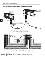
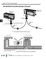
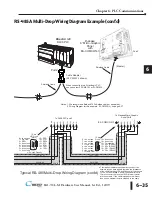
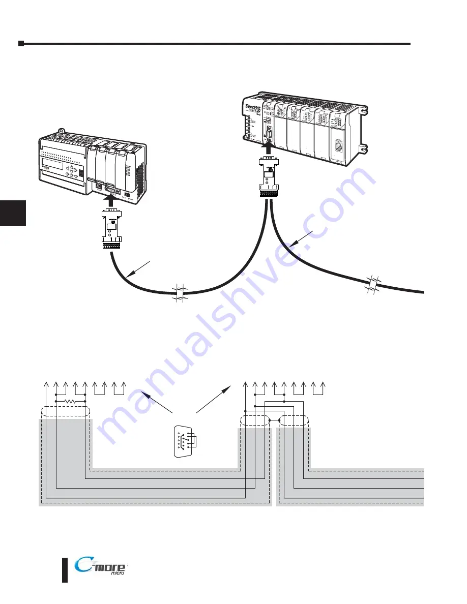
RS-485A Multi-Drop Wiring Diagram Example
shield
7
RTS+
CTS–
CTS+
RTS–
RXD+
TXD+
RXD–
TXD–
GND
Direct
LOGIC
DL205 PLC
Direct
LOGIC
DL06 PLC
HD = High Density
6 10 13 9 11 14 12 15
15-pin
HD D-sub
(male)
8 = do not use
7 = Sig GND
6 = RXD–
5 = do not use
4 = do not use
3 = do not use
2 = do not use
1 = do not use
15 = CTS–
14 = CTS+
13 = RXD+
12 = RTS-
11 = RTS+
10 = TXD–
9 = TXD+
1
6
15
7
RTS+
CTS–
CTS+
RTS–
RXD+
TXD+
RXD–
TXD–
GND
6 10 13 9 11 14 12 15
TXD+ / RXD+
TXD / RXD
Signal GND
TXD+ / RXD+
TXD / RXD
Signal GND
Typical RS-485 Multi-Drop Wiring Diagram
Port 2
Shielded Cable
Shielded Cable
To DL06 PLC port 2
Port 2
To D2-250-1 PLC port 2
*
* Termination resistors required at both ends of
the network to match the impedance of the cable
(between 100 and 500 ohms).
Cable Adapter
(ZL CMA15L shown)
When connecting to a DirectLogic PLC
use connector ZL-CMA15L or ZL-CMA15
Notes: 1. We recommend Belden 8103 shielded cable or equivalent.
2. Wiring Diagram for this example, ZL-CMA15(L), on page 6-27
RXD
RX
TX
SG
+5
V
TXD
23
RXD
TXD
ZL CMA15L
TX+
RS4 2/4 5
RX+
RXD
RX
TX
SG
+5
V
TXD
32
RXD
TXD
Z -CMA15
TX+
RS 22 48
RX+
ZL CMA15 or
ZL CMA15L
Содержание EA1-TCL-M
Страница 2: ......
Страница 4: ......
Страница 8: ......
Страница 14: ......
Страница 60: ......
Страница 66: ......
Страница 118: ......
Страница 125: ...Notes 7 7 Chapter 7 Maintenance 7 EA1 TCL M Hardware User Manual 1st Ed 12 09 ...
Страница 126: ......
Страница 169: ......
Страница 170: ...B B C MORE MICRO GRAPHIC PANEL RUNTIME ERRORS AP APPENDIX APPENDIX In This Appendix Introduction B 2 Panel Errors B 2 ...
Страница 179: ......

