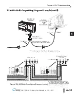
6–20
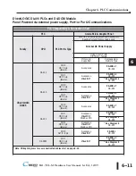
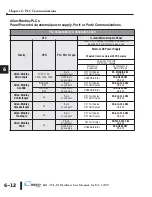
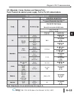
Chapter 6: PLC Communications
6
®
EA1-TCL-M Hardware User Manual, 1st Ed., 12/09
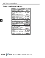
Cables from
AutomationDirect
- Wiring Diagrams (cont’d)
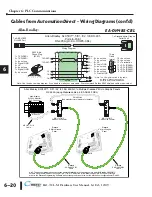
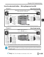
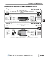
Allen-Bradley:
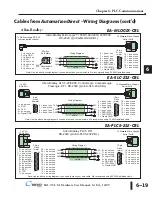
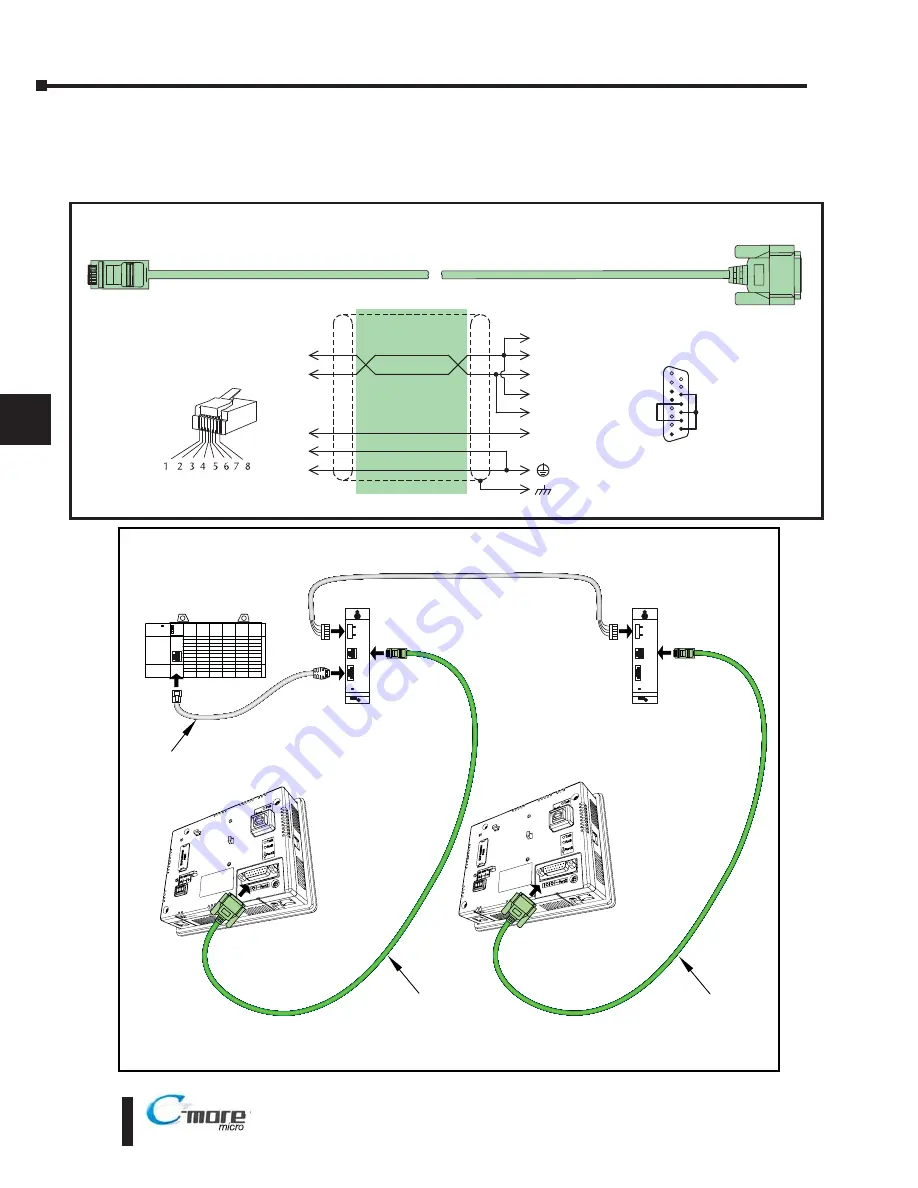
Allen-Bradley SLC500™, 5/01, /02, /03 DH-485
Point-to-Point
RS-485A (p/n EA-DH485-CBL)
8 = do not use
7 = do not use
6 = LE
5 = Logic GND
4 = do not use
3 = do not use
2 = do not use
1 = Frame GND
To AB SLC500
DH-485 Port
1
15 = do not use
14 = do not use
13 = Termination
12 = SD– (RS485)
11 = SD+ (RS485)
10 = RD– (RS485)
9 = RD+ (RS485)
1
15
1 = TXD/RXD+
2 = TXD/RXD–
3 = do not use
4 = Signal GND
5 = LE
6 = do not use
7 = Signal GND
8 = do not use
15-pin
D-sub
(male)
2
7
TXD/RXD+
TXD/RXD–
GND
9
10
5
1
RD+
RD–
shield
RJ45 8-pin
Phone Plug
(8P8C)
Wiring Diagram
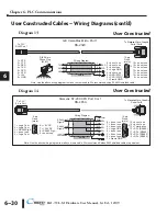
Note: Use the above wiring diagram if you need to make your own cable. We recommend Belden 9842 shielded cable or equivalent.
4
GND
11
12
13
SD+
SD–
Term.
5
LE *
6
LE *
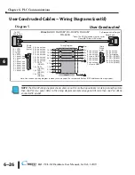
* Note: The LE signal is wired in the cable
as shown, but not required for
point-to-point communications.
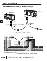
To
C-more
Micro-Graphic
Serial Port2
DH 485
Peripheral
CPU
J1
Power
Allen-Bradley
SLC 500 Modular
PLC Controller
DH-485 Link
(See manufacturer’s literature for details.)
AB 1747-AIC
DH485 Link Coupler
AB 1747-C11 A
Cable
J2
DH 485
Peripheral
CPU
J1
Power
J2
C-more
6” Micro-Graphic
Panel
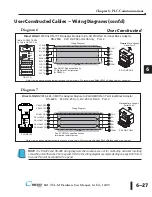
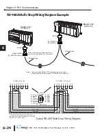
Note: The above diagram shows connecting multiple
C-more
Micro-Graphic panels to an Allen-Bradley DH485/AIC
network using the AB DH485 Link Coupler, p/n 1747-AIC. Select the “Allen-Bradly DH485/AIC SLC500 MircroLogix”
driver in the
C-more
Programming Software when starting the project. Also, set the AB channel configuration for DH485.
C-more
EA-DH485-CBL
Cable
C-more
EA-DH485-CBL
Cable
Allen Bradley SLC500™, 5/01, /02, /03 DH 485/AIC to Multiple
C-more
6” Micro Graphic Panels
RS 485A (using
C-more
cable p/n EA DH485 CBL)
AB 1747-AIC
DH485 Link Coupler
Channel 1 must be
set to DH485
Port2
C-more
6” Micro-Graphic
Panel
Port2
EA-DH485-CBL
Содержание EA1-TCL-M
Страница 2: ......
Страница 4: ......
Страница 8: ......
Страница 14: ......
Страница 60: ......
Страница 66: ......
Страница 118: ......
Страница 125: ...Notes 7 7 Chapter 7 Maintenance 7 EA1 TCL M Hardware User Manual 1st Ed 12 09 ...
Страница 126: ......
Страница 169: ......
Страница 170: ...B B C MORE MICRO GRAPHIC PANEL RUNTIME ERRORS AP APPENDIX APPENDIX In This Appendix Introduction B 2 Panel Errors B 2 ...
Страница 179: ......

