


Display Configuration | 11
Bosch Motorsport
DDU 10
85 / 188
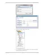
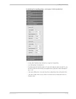
5.
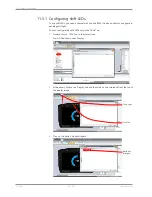
Define the relation between voltage and switch position and click on ‘Next’.
Voltage = 5000 x R/(R + 3010)
5000: Sensor supply (mV)
R: Resistor for each Rotary switch position (Ohm)
3010: Pull-up resistor (Ohm)
The following screenshot and the data are an example for a Bosch switch.
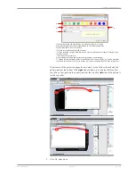
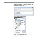
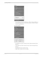
6.
Define minimum and maximum Limit.
Select “Output data type” from 8, 16 or 32 Bit.
Do not check “Use adjustment value”.
Choose the Measurement sheet and click on ‘Finish’.
Содержание DDU 10
Страница 1: ...Display DDU 10 Manual Version 1 0 14 03 2019 ...
Страница 67: ...Mechanical Drawing 10 Bosch Motorsport DDU 10 67 188 10 Mechanical Drawing ...
Страница 187: ...Bosch Motorsport DDU 10 187 188 ...
Страница 188: ...Bosch Engineering GmbH Motorsport Robert Bosch Allee 1 74232 Abstatt Germany www bosch motorsport com ...


