


6 | Analog and Frequency Inputs
28 / 188
DDU 10
Bosch Motorsport
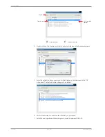
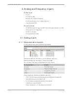
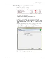
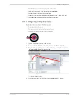
1st: Choose the
sensor´s category
2nd: To narrow your
choice, choose a
type
3rd: Select the
exact type
Opens sensor´s
datasheet
These calibration
values will be used
4.
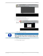
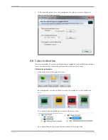
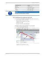
Click ‘Finish’ when done.
The “Create channel” window opens.
5.
Enter the channel name and description.
6.
Click ‘Ok’ when done.
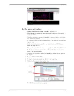
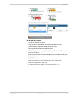
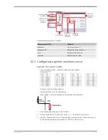
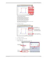
The channel is inserted into the DDU 10 Project Tree.
Channel is linked
to ANA03
Input pin Pull-up
resistor is activated
Calculation of
physical value with
characteristic curve
Available measurements for channel:
Measurement label
Function
raw_
name
mV value of sensor
raw_
name
_fi
Filtered mV value of sensor
name
Physical value of sensor
name
_fi
Filtered physical value
Содержание DDU 10
Страница 1: ...Display DDU 10 Manual Version 1 0 14 03 2019 ...
Страница 67: ...Mechanical Drawing 10 Bosch Motorsport DDU 10 67 188 10 Mechanical Drawing ...
Страница 187: ...Bosch Motorsport DDU 10 187 188 ...
Страница 188: ...Bosch Engineering GmbH Motorsport Robert Bosch Allee 1 74232 Abstatt Germany www bosch motorsport com ...


