Black Box ACX048 Скачать руководство пользователя страница 68

Page 68

724-746-5500   |   blackbox.com


Chapter 2: Overview 

3. Set the IP address of the SNMP server within Server Address.

4. Activate the requested traps by enabling them to “Y” (Yes).

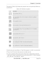
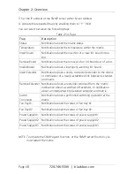
You can select between the following traps:

Table 2-54. Traps.

Trap

Description

Status

Notification about the matrix status.

Temperature

Notification about the temperature within the matrix.

Insert Board

Notification about the insertion of a new I/O board into a 
slot.

Remove Board

Notification about the removal of an I/O board out of a slot.

Invalid Board

Notification about a improperly-working I/O board.

Insert Extender

Notification about a newly-connected extender to the matrix 
or notification of a newly-established link between extender 
and matrix.

Remove Extender Notification about an extender removed from the matrix,  

notification about a switched off extender, or notification 
about an interrupted link between extender and matrix.

Switch 
Command

Notification about a performed switching operation at the 
matrix.

Fan Tray #1

Notification about the status of fan tray #1.

Fan Tray #2

Notification about the status of fan tray #2.

Power Supply #1 Notification about the status of power supply #1.

Power Supply #2 Notification about the status of power supply #2.

Power Supply #3 Notification about the status of power supply #3.

NOTE:  To activate the SNMP agent function, or the SNMP server function, you 

must restart the matrix.

Содержание ACX048

Страница 1: ...746 5500 FREE technical support 24 hours a day 7 days a week Call 724 746 5500 or fax 724 746 0746 Mailing address Black Box Corporation 1000 Park Drive Lawrence PA 15055 1018 Web site www blackbox c...

Страница 2: ...the ServSwitch DKM FX Compact function in similar ways The difference between them is described in the table below Table 1 ServSwitch DKM FX and DKM FX Compact comparison ServSwitch DKM FX Compact Ser...

Страница 3: ...uired to take whatever measures may be necessary to correct the interference Changes or modifications not expressly approved by the party responsible for compliance could void the user s authority to...

Страница 4: ...debe colocar en libreros o gabinetes que impidan el flujo de aire por los orificios de ventilaci n 10 El equipo el ctrico deber ser situado fuera del alcance de fuentes de calor como radiadores regist...

Страница 5: ...ci n 18 Servicio por personal calificado deber ser provisto cuando A El cable de poder o el contacto ha sido da ado u B Objectos han ca do o l quido ha sido derramado dentro del aparato o C El aparato...

Страница 6: ...lets In each case make sure that the ground connection is maintained from the outlet socket to the power supply s AC power input Do not connect the link interface to any other equipment particularly n...

Страница 7: ...nd MTBF 17 2 Overview 21 2 1 Description 21 2 1 1 Application 21 2 1 2 Access Options 22 2 2 System Overview 22 2 3 Available Products 24 2 4 What s Included 26 2 5 Device Views 27 2 5 1 ServSwitch DK...

Страница 8: ...orts ACXC48F32 44 2 6 Diagnostics and Status 45 2 6 1 Status LEDs 45 2 6 2 Port Status 53 2 6 3 Port Status Matrix Grid 57 2 6 4 Extender OSD 58 2 6 5 Network Status 59 2 6 6 Firmware Status 61 2 6 7...

Страница 9: ...3 Deleting Flex Port Extender Units 131 4 6 4 Deleting Fixed Port Extender Units 131 4 7 USB 2 0 131 4 8 CPU Settings 134 4 9 Console Settings 139 4 9 1 CON Devices 139 4 9 2 Mouse and Keyboard 143 4...

Страница 10: ...ed Switching 191 5 4 CON Switch 196 5 5 Multi Screen Control 198 5 6 USB 2 0 Switching 199 5 7 Presets 199 5 8 Serial Interface 199 5 9 Power On and Power Down Functions 201 5 9 1 Restart 201 5 9 2 Fa...

Страница 11: ...D devices on the DVI and USB HID cards Mouse Compatible with most 2 button 3 button and scroll mice Other USB HID devices The proprietary USB emulation also supports certain other USB HID devices such...

Страница 12: ...SD handling precautions 1 1 7 SDI Interconnect SDI device communication requires a mini coax connection with mini BNC connectors or 3G SFPs with transmission speeds of 0 360 Gbps SD SDI SMPTE 259M 1 4...

Страница 13: ...ance is cut in half Table 1 2 Maximum acceptable cable length Cable Type Distance CATx 24 AWG solid conductor cable 400 ft 140 m CATx 26 8 AWG stranded conductor cable 200 ft 70 m 1 2 2 Fiber NOTE A p...

Страница 14: ...mode fiber optic cable you can double the maximum acceptable cable length Type of Connector The fiber cable uses LC connectors 1 2 3 Coaxial NOTE A point to point connection is necessary Table 1 5 Coa...

Страница 15: ...S data 0 3 T M D S data 2 GND 11 T M D S data 1 GND 19 T M D S data 0 GND 4 Not connnected 12 Not connected 20 Not connected 5 Not connected 13 Not connected 21 Not connected 6 DDC input SCL 14 5 VDC...

Страница 16: ...t connected 5 GND Table 1 10 RJ 45 connector Picture Pin Signal Color Signal 1 D1 5 Not connected 2 D1 6 D2 3 D2 7 Not connected 4 Not connected 8 Not connected 1 3 2 I O Board CATx Table 1 11 RJ 45 C...

Страница 17: ...0 VAC 50 60 Hz ACXC80 ACXC80F ACXC48F32 Max 125 W ACXC64 ACXC64F ACXC48F16 Max 105 W ACXC48 ACXC48F Max 90 W ACXC32 ACXC32F Max 65 W ACXC16 ACXC16F Max 40 W ACXC8 ACXC8F Max 13 W ACX048 5 A 94 W max w...

Страница 18: ...1 7 H x 8 75 W x 5 75 D 4 3 x 22 3 x 14 6 cm ACXC48 ACXC48F ACXC32 ACXC32F ACXC16 ACXC16F 1 7 H x 17 4 W x 16 9 D 4 4 x 44 4 x 42 9 cm ACXC48F16 ACXC48F32 ACXC64 ACXC64F ACXC80 ACXC80F 3 4 H x 17 48 W...

Страница 19: ...efore the MTBF calculation refers to an ambient temperature of 45 C The humidity is limited to 60 ACX288 260 000 POH ACX160 310 000 POH ACX080 320 000 POH ACX048 350 000 POH CPU board 480 000 POH I O...

Страница 20: ...Chassis 133 400 Per fan 280 000 POH Per PSU 295 700 ACXC32 Chassis 165 300 Per fan 280 000 POH Per PSU 295 700 ACXC32F Chassis 161 200 Per fan 280 000 POH Per PSU 295 700 ACXC16 Chassis 208 322 Per f...

Страница 21: ...using the ACXC16 32 using the ACXC32 48 using the ACXC48 48 CATx ports 16 SFP slots using the ACXC48F16 or 48 CATx ports 32 SFP slots using the ACXC48F32 64 CATx using the ACXC64 or 80 CATx using the...

Страница 22: ...CON units The ServSwitch connects to the CPU units CON units by interconnect cables copper or fiber or is connected directly to the video devices when used as a video matrix The CPU units connect dir...

Страница 23: ...G LINK USB HID DVI D 5V DC 5V DC PROG LINK USB HID DVI D 5V DC 5V DC PROG LINK USB HID DVI D 5V DC 5V DC PROG LINK USB HID DVI D 1 2 3 4 3 5 6 Figure 2 1 System overview Table 2 2 System components Nu...

Страница 24: ...h DKM FX Compact 48 port CATx ACXC48F ServSwitch DKM FX Compact 48 port 48 SFP slots ACXC48F16 ServSwitch DKM FX Compact 48 CATX ports 16 SFP slots ACXC48F32 ServSwitch DKM FX Compact 48 CATx ports 32...

Страница 25: ...D SDI 3G SDI CATx transmitter card ACXSDI SM R SDI fiber receiver card ACXSDI3G SM R HD SDI 3G SDI fiber receiver card ACXSDI CX R SDI CATx receiver card ACX288 FAN Fan for the 160 288 port chassis AC...

Страница 26: ...rt at 724 746 5500 or info blackbox com ACX048 ACX080 ACX160 ACX288 ACXC8 ACXC8F ACXC16 ACXC16F ACXC32 ACXC32F ACXC48 ACXC48F ACXC48F16 ACXC48F32 ACXC64 ACXC64F ACXC80 ACXC80F DKM FX or DKM FX Compact...

Страница 27: ...are fully populated with I O cards and are intended to be example diagrams The chassis do not come with any I O cards You need to purchase the I O cards separately 2 5 1 ServSwitch DKM FX 48 Port ACX0...

Страница 28: ...80 Port ACX080 1 2 3 4 5 6 7 Figure 2 3 Front view ACX080 Table 2 5 ACX080 components Number Component 1 Slot for fan tray 2 Slot for Power Supply Unit 1 3 Slot for I O Boards 1 10 4 Slot for Power Su...

Страница 29: ...60 1 2 3 4 5 6 8 7 Figure 2 4 Front view ACX160 Table 2 6 ACX160 components Number Component 1 Slot for Power Supply Unit 1 2 Slot for Fan Tray 1 3 Slot for Power Supply Unit 2 4 Slot for Fan Tray 2 5...

Страница 30: ...Page 30 724 746 5500 blackbox com Chapter 2 Overview 2 5 4 ServSwitch DKM FX 288 Port ACX288 1 2 3 4 5 6 7 8 Figure 2 5 Front view ACX288...

Страница 31: ...O Boards 1 36 6 Slot for Power Supply Unit 3 7 Grounding 8 Slot for CPU board NOTE The ServSwitch DKM FX Compact models are described next 2 5 5 ServSwitch DKM FX Compact 8 Port CATx ACXC8 Figure 2 6...

Страница 32: ...itch DKM FX Compact 8 Port SFP ACXC8F Figure 2 7 Front view ACXC8F Table 2 9 ACXC8F components Number Component 1 I O ports 1 8 SFP 2 Serial connection RJ 45 3 Network connection RJ 45 4 Connect to po...

Страница 33: ...2 3 Figure 2 8 Front view ACXC16 Table 2 10 ACXC16 components Number Component 1 I O ports 1 16 CATx 2 Serial connection RJ 45 3 Network connection RJ 45 1 2 3 Figure 2 9 Back view ACXC16 Table 2 11...

Страница 34: ...1 2 3 Figure 2 10 Front view ACXC16F Table 2 12 ACXC16F components Number Component 1 I O ports 1 16 SFP 2 Serial connection RJ 45 3 Network connection RJ 45 1 2 3 Figure 2 11 Back view ACXC16F Table...

Страница 35: ...2 12 Front view ACXC32 Table 2 14 ACXC32 components Number Component 1 I O ports 1 16 CATx 2 I O ports 17 32 CATx 3 Serial connection RJ 45 4 Network connection RJ 45 1 2 3 Figure 2 13 Back view ACXC3...

Страница 36: ...2 14 Front view ACXC32F Table 2 16 ACXC32F components Number Component 1 I O ports 1 16 SFP 2 I O ports 17 32 SFP 3 Serial connection RJ 45 4 Network connection RJ 45 1 2 3 Figure 2 15 Back view ACXC...

Страница 37: ...ACXC48 Table 2 18 ACXC48 front panel components Number Component 1 I O ports 1 16 CATx 2 I O ports 17 32 CATx 3 I O ports 33 48 CATx 4 Serial connection RJ 45 5 Network connection RJ 45 1 2 3 Figure 2...

Страница 38: ...iew ACXC48F Table 2 20 ACXC48F front panel components Number Component 1 I O ports 1 16 SFP 2 I O ports 17 32 SFP 3 I O ports 33 48 SFP 4 Serial connection RJ 45 5 Network connection RJ 45 1 2 3 Figur...

Страница 39: ...e 2 22 ACXC64 components Number Component 1 I O ports 1 16 CATx 2 I O ports 49 64 CATx 3 I O ports 17 32 CATx 4 I O ports 33 48 CATx 5 Serial connection RJ 45 6 Network connection RJ 45 Figure 2 21 Ba...

Страница 40: ...64F Table 2 24 ACXC64F components Number Component 1 I O ports 1 16 SFP 2 I O ports 49 64 SFP 3 I O ports 17 32 SFP 4 I O ports 33 48 SFP 5 Serial connection RJ 45 6 Network connection RJ 45 Figure 2...

Страница 41: ...CXC80 components Number Component 1 I O ports 1 16 CATx 2 I O ports 49 64 CATx 3 I O ports 17 32 CATx 4 I O ports 65 80 CATx 5 I O ports 33 48 CATx 6 Serial connection RJ 45 7 Network connection RJ 45...

Страница 42: ...2 28 ACXC80F components Number Component 1 I O ports 1 16 SFP 2 I O ports 49 64 SFP 3 I O ports 17 32 SFP 4 I O ports 65 80 SFP 5 I O ports 33 48 SFP 6 Serial connection RJ 45 7 Network connection RJ...

Страница 43: ...CXC48F16 Table 2 30 ACXC48F16 components Number Component 1 I O ports 1 16 CATx 2 I O ports 49 64 SFP 3 I O ports 17 32 CATx 4 I O ports 33 48 CATx 5 Serial connection RJ 45 6 Network connection RJ 45...

Страница 44: ...ble 2 32 ACXC48F32 components Number Component 1 I O ports 1 16 CATx 2 I O ports 49 64 SFP 3 I O ports 17 32 CATx 4 I O ports 65 80 SFP 5 I O ports 33 48 CATx 6 Serial connection RJ 45 7 Network conne...

Страница 45: ...apter 2 Overview 2 6 Diagnostics and Status 2 6 1 Status LEDs The ServSwitch DKM FX and DKM FX Compact LED indicators are shown in Figures 2 12 through 2 22 and described in Tables 2 14 through 2 25 1...

Страница 46: ...d flashing Registration is in progess Green flashing Operating condition Green CPU board de registered 2 Status 2 White CPU board is in registration process Red flashing Registration at the matrix is...

Страница 47: ...Blue I O board in registration process Blue flashing Operating condition communication active with CPU board active Red flashing I O board de registered locking pin pulled out CATx SFP fiber SFP coax...

Страница 48: ...tatus LEDs on the fan tray Table 2 37 Status LEDs on the fan tray Number LED Status Description 1 Status 1 green On Operating condition 2 Status 2 blue Off Operating condition On Error indication 3 Ho...

Страница 49: ...tus Description 1 AC input OK green On Operating condition 2 DC output OK green On Operating condition 3 O T yellow Off Normal temperature On High temperature 1 Figure 2 37 Status LEDs on the power su...

Страница 50: ...pe varies white might also appear as light purple or light blue LAN Port LEDs on the ACXC8 ACXC8F ACXC16 ACXC16F ACXC32 ACXC32F ACXC48 ACXC48F16 ACXC38F32 ACXC64 ACXC64F ACXC80 ACXC80F 1 2 Number LED...

Страница 51: ...t 2 Table 2 38 Status LEDs at the ports of the ACXI08 C ACXI08 SM ACXI08 SFP I O boards Number LED Status Description 1 Link status Off Initialization Green Connection via interconnect cable is OK dat...

Страница 52: ...ACXC38F32 ACXC64 ACXC64F ACXC80 ACXC80F 1 2 1 2 Number LED Status Description 1 Left Fan Status 1 red On Error indication Off Operating condition 2 Left Fan Status 2 green On Operating condition Off F...

Страница 53: ...etween the various consoles and CPUs are shown in this menu You can access the menu via Java Figure 2 39 OSD and Java icons Java Tool The current port configuration of the ServSwitch DKM FX is illustr...

Страница 54: ...m Chapter 2 Overview Figure 2 41 Menu Status Matrix View screen Example 1 Table 2 41 Connection status Color Description Gray Port not connected Yellow Video connection Green KVM connection Red Faulty...

Страница 55: ...ed to a CON unit that is connected to a CPU unit in Private Mode see Section 3 7 3 Port connected to a USB 2 0 CPU unit Port connected t a USB 2 0 CON unit Port is configured as a CON port for custome...

Страница 56: ...e Name of the connected console or CPU Connections Listing of assigned connections to the marked port full access or video access NOTE To open the context menu for the currently selected port with fur...

Страница 57: ...in an optimized view of 24 ports per line in order to be able to show also a larger number of ports You have the following option to access the menu Figure 2 42 Java Tool The current port configurati...

Страница 58: ...me of the currently connected CPU Access Full Access The extender s indivdual console has a KVM connection to the displayed CPU Video Access The extender s individual console has a video only connecti...

Страница 59: ...rol will be displayed at those consoles that do not have K M control at the moment The console is displayed in a yellow color under Access 2 6 5 Network Status The current network configuration is sho...

Страница 60: ...provided manually or via DHCP Subnet mask Information about the subnet mask as provided manually or via DHCP Gateway Information about the gateway address as provided manually or via DHCP MAC ID Infor...

Страница 61: ...n this menu You can access the menu via OSD or Java Figure 2 47 OSD and Java icons Figure 2 48 Menu status firmware Table 2 49 Menu status firmware Field Description Name Description of the modules Ty...

Страница 62: ...overall status of the ServSwitch DKM FX and store it locally file extension zip select Switch Save Status to File or press the respective button in the symbol bar The various modules can expanded and...

Страница 63: ...a Tool icon The following information is shown in this menu Table 2 50 Menu status firmware status extender Field Description Name Description of the firmware Type Description of the extender module P...

Страница 64: ...ion Field Description Date Datestamp Time Timestamp Message Detailed description of the event Trace possibilities Select Status Trace IO Board in the main menu to check the events on your current I O...

Страница 65: ...vities are written continuously into logging files and stored locally This process can be set with various options Options Select Extras Options in the menu bar and open the Syslog tab The following o...

Страница 66: ...ltered Facility Messages of a defined facility will be filtered Severity Messages of a defined severity will be filtered Host Messages of a defined host will be filtered Message Messages with defined...

Страница 67: ...e main menu Figure 2 56 2 Set the Enable option to Y Yes under SNMP Agent Activating this option grants permission to run an active query of the SNMP agent To activate the SNMP agent proceed as follow...

Страница 68: ...otification about a newly connected extender to the matrix or notification of a newly established link between extender and matrix Remove Extender Notification about an extender removed from the matri...

Страница 69: ...permission for an active query of the SNMP agent To configure an SNMP server proceed as follows 1 Select Configuration Network in the task area 2 Activate the Enable Traps option within SNMP Server Th...

Страница 70: ...The following configuration parts are checked Matrix Firmware Extender Firmware Multi Screen Control Ext Units CPU Devices CON Devices User System Configuration The following notification levels can b...

Страница 71: ...the messages WARNING and ERROR are created by the System Check function the problem will be described and a basic guideline will be provided To start System Check proceed as follows Select the symbol...

Страница 72: ...vSwitch DKM FX 1 Install the CPU and I O boards 2 Connect the keyboard mouse and monitor to the CPU board of the ServSwitch DKM FX 3 Connect the ServSwitch DKM FX to the power supply 4 Open OSD via ho...

Страница 73: ...the configuration and check the box that says Activate configuration after upload then press Finish The DKM will reboot and the new configuration will be active 6 Optional Establish a network connect...

Страница 74: ...cess via OSD by the keyboard connected to the CPU board or an extender CON unit you have the following access options via Java Tool via serial interface A connection to common media controls is possib...

Страница 75: ...nsole However you can control the system only at Monitor 1 Any signal source can be switched to any number of monitors that will show the video signal at the same time Even optional audio can be switc...

Страница 76: ...rallel operation stacking of several ServSwitch DKM FX devices One of the DKM FX or DKM FX Compact matrices has to be defined as the master matrix All the others have to be configured as slave matrice...

Страница 77: ...of up to 16 matrices To build a matrix grid the grid matrices are interconnected by Grid Lines In this case the slave matrices can be connected directly to the master matrix or between themselves Whe...

Страница 78: ...Page 78 724 746 5500 blackbox com Chapter 3 Installation Figure 3 4 Matrix Grid...

Страница 79: ...are dynamically configured to support connections in both directions To access cascaded matrices from a console one of the matrices must be config ured as a sub matrix 1 2 3 4 3 5 3 6 7 Figure 3 5 Cas...

Страница 80: ...available NOTE If there is no keyboard command executed within 10 seconds after activating Command Mode it willl be automatically deactivated The following table lists the keyboard commands to enter e...

Страница 81: ...t to the physical keyboard and mouse at the user station will execute the hotkeys and not pass them on to the DKM FX or DKM FXC Set freely selectable Hotkey exemplary To set a freely selectable Hotkey...

Страница 82: ...tion and operation via Java Tool configuration and operation via serial interface operation only 4 2 1 Control via OSD Figure 4 1 OSD icon Via OSD on screen display you can set the configuration of th...

Страница 83: ...ress F7 Leaving OSD Press the Esc key in the main menu or simultaneously press Left Shift Esc anywhere within the OSD The OSD will close without any further changes and the currently active CPU connec...

Страница 84: ...In input fields Line down with wrap around In menus Line down without wrap around Cursor Down Previous page in menus with more than one page Page Up Next page in menus with more than one page Page Dow...

Страница 85: ...in a descending order or in an ascending order by pressing the keyboard command twice Name F2 Go to the next result in the list of results for the search field Next F3 Go to the previous result in th...

Страница 86: ...unt there is no way to retrieve it We recommend that you set up a second admin account and keep the credentials in a safe place 4 2 2 Control via Java Tool Figure 4 4 Java icon Requirements If you wan...

Страница 87: ...cross wired network cable For a connection between the computer and ServSwitch DKM FX via switch or hub use a straight pinned network cable Do not use a network connection between Java Tool and matrix...

Страница 88: ...e time because available sockets are limited When you are done using the Java Tool be sure to correctly disconnect logout from the switch If you close the Java Tool before disconnecting from the switc...

Страница 89: ...b bar third line Task area left menu section Working area right menu section Status bar bottom line section Operating Instructions The operation of the Java tool is intuitive and corresponds to the us...

Страница 90: ...ble 4 7 Keyboard commands Function Keyboard command Cursor to the left Cursor Left Cursor to the right Cursor Right Line up Cursor Up Line down Cursor Down Previous page in input or status menus with...

Страница 91: ...ions that support a user friendly and effective operation of the tool The context functions are described in the respective chapters To execute a context function use the right mouse button on the cor...

Страница 92: ...in off line mode without a direct connection between ServSwitch DKM FX and Java tool To activate a configuration in the ServSwitch DKM FX 1 Select File Upload to in the menu bar 2 Enter the IP addres...

Страница 93: ...he lower part of the working area You can also activate the online configuration mode by clicking on the gear icon in the shortcut tool bar 2 Make any changes in the configuration and system settings...

Страница 94: ...macro files To set various font sizes for the Java tool proceed as follows 1 Select Extras Options in the menu bar 2 Open the Font tab 3 Select the desired font size normal or large Report The Java t...

Страница 95: ...ams for switching single or all connections available both unidirectional and bidirectional There are also telegrams for an overall definition of the total switching status and for saving and loading...

Страница 96: ...U You can assign virtual to real CPUs in this menu Switch several consoles to the same CPU If there are several consoles connected to a virtual CPU that is assigned to a real CPU you will only have to...

Страница 97: ...eal CPU 2 Press the Edit button 3 Select the CPU in the list Real Devices that has to be assigned to the selected virtual CPU 4 Press the OK button to confirm the assignment The assignment will be don...

Страница 98: ...ngle consoles from a larger pool of consoles The Java tool also offers the possibility to go directly from the Assignment menu to the Definition menu to check specific settings for the respective cons...

Страница 99: ...gnments Virtual CON Devices For an assignment proceed as follows 1 From the Real Devices list select the real console that has to be assigned to a virtual CPU 2 Press the Edit button 3 Select the virt...

Страница 100: ...e table 2 Double click in the Virtual Console column to get a list of all available virtual consoles 3 Select the required virtual console You can select between the following buttons Table 4 10 Send...

Страница 101: ...ce name of the matrix default SWITCH 01 Name Text Enter the name of the configuration that is used to save the current settings default Standard Info Text Additional text field to describe the configu...

Страница 102: ...media control via the serial interface Deactivated Function not active default Slave matrix Activated Synchronize the slave matrix according to the switch status of the master matrix Deactivated Func...

Страница 103: ...box com Chapter 4 Configuration OSD Select Configuration System in the main menu Figure 4 17 Menu Configuration System screen Table 4 12 Cancel and Okay selection buttons Button Function Cancel Reject...

Страница 104: ...uration Java Tool Figure 4 18 Menu System System Data 4 4 2 Automatic ID From this menu you can automatically create CPU and CON devices settings by connecting a new extender unit You can access the m...

Страница 105: ...e ID Real CPU Device Numerical value Initial value of the automatic ID for real CPUs default value 1000 ID Virtual CPU Device Numerical value Initial value of the automatic ID for virtual CPUs default...

Страница 106: ...ttons Button Function Cancel Reject changes Okay Save changes Java Tool Select System Automatic ID in the task area Figure 4 21 Menu System Automatic ID screen 4 4 3 Access The access configuration is...

Страница 107: ...ted Newly created users automatically receive access to all CPUs deactivated Function not active default Enable new CON activated Newly created CON devices automatically receive access to all CPUs dea...

Страница 108: ...iguration OSD Select Configuration Access in the main menu Figure 4 23 Menu Configuration Access screen You can select between the following buttons Table 4 16 Cancel and Save selection buttons Button...

Страница 109: ...ion Java Tool Select System Access in the task area Figure 4 24 Menu System Access screen 4 4 4 Switch The configuration of the switching parameters is set in this menu You have the following possibil...

Страница 110: ...tivated Deactivated Function not active default Force Disconnect Activated Extension of Force Connect If the user connects to a CPU as an operator that is already related to another user the connectio...

Страница 111: ...to the CPU NOTE Set 0 for an immediate transfer in real time Only one console can have keyboard and mouse control at the same time The other consoles that are connected to the same CPU have a video on...

Страница 112: ...on buttons Button Function Cancel Reject changes Save Save changes Java Tool Select System Switch in the task area Figure 4 27 Menu system switch 4 4 5 Network The network configuration is set in this...

Страница 113: ...ion not active Syslog server Byte Input of the IP address of the Syslog server in the form 192 168 1 1 Trace DEB Activate debug messages in Trace default Yes NOTE The debug messages are exclusively fo...

Страница 114: ...t your system administrator before modifying the network parameters Otherwise unexpected results and failures can occur in combination with the network OSD Select Configuration Network in the main men...

Страница 115: ...Configuration Java Tool Select System Network in the task area Figure 4 30 Menu system network 4 4 6 Date and Time Date and Time are set in this menu based on Simple Network Time Protocol SNTP You can...

Страница 116: ...activated Function not active default SNTP Server Byte Input of the SNTP server IP address default 000 000 000 000 Month 1 12 Enter month Date 1 31 Enter date Year 1 99 Enter year Day 1 7 Enter day of...

Страница 117: ...3 Select your time zone in the field Time Zone 4 Press the OK button to confirm your settings 5 Restart the matrix The system time will be now be by the SNTP server To set the real time clock without...

Страница 118: ...SNTP proceed as follows 1 Set the current date in the field Date and Time 2 Set the current time in the field Day and Time 3 Press the Apply button to set the system time 4 Option If you want to recei...

Страница 119: ...rowser Deactivated Function not active default Power User activated User has rights Permission for crosspoint operations deactivated Function not active default Super User activated Permission for sys...

Страница 120: ...tion OSD Select Configuration User in the main menu Figure 4 35 Menu Configuration User screen Table 4 24 OSD settings Button Function New Create a new user Edit Edit an existing user Delete Delete an...

Страница 121: ...pply Create a new user account Cancel Reject changes To configure user access rights for CPUs proceed as follows 1 Select a user in the User list 2 By using the right mouse button once on a CPU in one...

Страница 122: ...ct between the following keyboard commands Table 4 26 Keyboard commands Function Keyboard Command Add CPU to Full Access list F Add CPU to Video Access list V Add CPU to No Access list N NOTE To selec...

Страница 123: ...vorites list for you own user proceed as follows 1 Select CPUs from the list CPU Devices that have to be moved to the Favorites list By pressing the a key a CPU device will be moved to the Favorites l...

Страница 124: ...to add to the Favorites list CPU assigned Press the Ctrl key to mark more than one CPU device 2 Press the button to move the marked CPU devices to the Favorites list Press the button to move the firs...

Страница 125: ...nect Video P1 CON P2 CPU Set video connection from console P1 to CPU P2 Disconnect P1 CON Disconnect console P1 Logout User Logout current user Set Real CPU P1 VCPU P2 RCPU Assign a virtual CPU to a r...

Страница 126: ...r from the Configuration User Macros in the main menu Figure 4 41 Menu Configuration User Macros To create a macro for the selected user proceed as follows 1 Select the key for which a macro has to be...

Страница 127: ...lect the user for which macros have to be created and open the tab Macros Figure 4 42 Menu Definition User To create a macro for the selected user proceed as follows 1 Select the Key 1 16 for which a...

Страница 128: ...u This also contains the creation of new extender units and the deletion of existing extender units The extender unit describes the connection of a physical extender to the matrix Every extender board...

Страница 129: ...uration EXT Units screen You can select between the following buttons Table 4 29 Extender EXT units settings Button Function New Create an extender unit Edit Edit an existing extender unit Delete Dele...

Страница 130: ...n Function New Create a new extender unit Delete Delete an existing unit Apply Confirm changes of an extender unit Cancel Reject changes 4 6 1 Creating Flex Port Extender Units Extenders with ID funct...

Страница 131: ...rs the I O board will need to be restarted otherwise it will not function properly 4 6 3 Deleting Flex Port Extender Units Deleting Flex Port extender units connected to the matrix is not possible 4 6...

Страница 132: ...An extender with an eight digit ID will be created starting with digit 9 2 Assign an appropriate name to the extender in the Name field 3 Enter the port number of the matrix physically connected to t...

Страница 133: ...0 CON extender from the EXT available field into the EXT assigned field 7 Give an appropriate name to the new Device in the Name field 8 Repeat steps 6 and 7 for all USB 2 0 CPU extenders in the Conf...

Страница 134: ...assigned to an existing CON Device in the Definition CPU Devices menu or a new CON Device has to be created for the assignment by pressing the New button 8 If you use parallel operation within the ma...

Страница 135: ...e of the CPU device Virtual Device Activated Create new CPU device as a virtual one Deactivated Function not active default Allow Private Activated Allows switching to the respective CPU device in Pri...

Страница 136: ...ure 4 50 Menu Configuration CPU Devices screen You can select between the following buttons Table 4 32 CPU unit buttons Button Function New R Create a new real CPU unit New V Create a new virtual CPU...

Страница 137: ...evices screen You can select between the following buttons Table 4 33 CPU devices buttons Button Function New Create a new CPU device Delete Delete a new CPU device Apply Confirm a created CPU device...

Страница 138: ...all parameters that are relevant for the CPU 5 To confirm the new CPU press the Apply button To access a new CPU via matrix an assignment of one or more CPU type extender units is required Proceed as...

Страница 139: ...unction not active Force login Activated Force user login at this CON device Deactivated Function not active LOS frame Activated If there is a loss of connection the last picture shown will still be d...

Страница 140: ...enu Figure 4 53 Menu Configuration CON Devices screen You can select between the following buttons Table 4 36 CON devices buttons Button Function New R Create a real console New V Create a virtual con...

Страница 141: ...iguration CON Devices screen Table 4 37 Menu configuration CON devices buttons Button Function New Open a new CON device Delete Delete a new CON device Apply Confirm a created CON device Cancel Reject...

Страница 142: ...the Apply button To run a created CPU via matrix you need to assign one or more CON units extenders To place an assignment proceed as follows 1 Select the console in the CON devices list to be assign...

Страница 143: ...set the OSD configuration for mouse and keyboard You can access the menu via OSD or Java Figure 4 55 OSD and Java icons Table 4 40 Mouse and keyboard settings Field Selection Description Horizontal s...

Страница 144: ...ter 4 Configuration OSD Select Configuration EXT Units in the main menu Figure 4 56 Menu Configuration EXT Units screen You can select between the following buttons Table 4 41 Buttons Button Function...

Страница 145: ...724 746 5500 blackbox com Chapter 4 Configuration Java Tool Select Definition EXT Units in the task area NOTE Set mouse and keyboard settings using the OSD Data tab Figure 4 57 Menu Definition EXT Uni...

Страница 146: ...able Extender OSD default Yes Deactivated Function not active Update connection info Activated Update connection changes during fade in of Extender OSD default Yes Deactivated Function not active Disp...

Страница 147: ...igure 4 59 Menu Configuration EXT Units To change the Extender OSD settings proceed as follows 1 Select the console extender in the list EXT Units whose Extender OSD settings has to be adjusted 2 When...

Страница 148: ...ender OSD settings have to be adjusted 2 Open the Extender OSD Data tab 3 Adjust the desired settings and confirm by pressing the Apply button 4 9 4 Favorite List Consoles Individual Favorites lists o...

Страница 149: ...our own console proceed as follows 1 Select successively the CPUs from the list CPU Devices that have to be moved to the Favorites list Press the a key to move a CPU device to the Favorites list Press...

Страница 150: ...To mark more than one CPU device at the same time press the Ctrl key 2 Press the button to move the marked CPU devices to the Favorites list If you press the button the first eight CPU devices from th...

Страница 151: ...P1 VCPU P2 RCPU Assign a virtual CPU to a real CPU Set Virtual CON P1 RCON P2 VCON Assign a real console to a virtual console Push P1 CON The KVM connection is forwarded to Console P1 and is changed t...

Страница 152: ...e macro has to be created Figure 4 65 Menu Configuration CON Macros To create a macro for the selected console proceed as follows 1 Select the number key 1 16 for which a macro has to be created 2 Sel...

Страница 153: ...to be created and open the Macros tab Figure 4 66 Menu Definition CON Devices To create a macro for the selected console proceed as follows 1 Select the number key 1 16 for which a macro has to be cr...

Страница 154: ...e Reset Key Macros function 4 9 6 Parallel Operation This section explains how to configure the parallel operation of a CPU Device by two or more CON Devices Only one CON Device at a time can control...

Страница 155: ...as follows 1 Activate the Enable Video Sharing function 2 Activate the Force Connect function 3 Activate the Keyboard Connect function if taking over control by a keyboard event should be possible 4 A...

Страница 156: ...Connect function if taking over control by a keyboard event should be possible 4 Activate the Mouse Connect function if taking over control by a keyboard movement should be possible 5 Define a Releas...

Страница 157: ...eyboard commands NOTE To enable Multi Screen Control all Extender Units assigned to the CON device must be physically connected to the same block of four ports consecutively on the I O board of the ma...

Страница 158: ...hat uses the Multi Screen Control 4 Select one or more control displays within the CON Device by setting the function Control as Y in the respective display field Control displays are referred to the...

Страница 159: ...unit 2 Activate the Manual option and the USB HID switching will only be allowed by using keyboard commands With manual switching you can use multi head consoles 3 In the Arrangement field select the...

Страница 160: ...access the menu Figure 4 72 OSD button Select Configuration Save in the main menu By selecting this menu item the active configuration of the matrix is saved to the permanent matrix memory By default...

Страница 161: ...the current configuration must be selected explicitly Afterwards the current configuration will be saved to this storage location and will be immediately shown in the menu The previously saved configu...

Страница 162: ...onfirm the inputs Press the Next button 3 Select the storage location where the configuration will be saved default or config01 config08 Press the OK button to confirm Figure 4 75 Menu File Upload to...

Страница 163: ...ed from eight personalizable configurations and the default settings The selected configuration will be immediately loaded and displayed in the menu as Active The previously active configuration is de...

Страница 164: ...guration 3 Load the configuration by pressing the Activate button Figure 4 78 Menu Administration Activate Configuration on Switch screen 4 10 4 Saving of Configurations External Created configuration...

Страница 165: ...llowing possibilities to load configurations from files 1 Select File Open during off line mode and select the storage location of the configuration file that has to be opened 2 Open the configuration...

Страница 166: ...Switch DKM FX offers the possibility to read out available configuration lists extender CPUs consoles and users for exporting and importing again via Java tool You have the following possibilities to...

Страница 167: ...CPU Console or User 3 Select the storage location for the export file 4 Confirm the export with the Finish button Figure 4 83 Menu File Export screen 4 11 2 Import Options Configuration lists are impo...

Страница 168: ...of ports in the entire system has to be increased or if certain important connections should be distributed to several matrices because of redundancy The Tie Lines are unidirectional and can only be u...

Страница 169: ...86 Menu configuration EXT units 1 Press the New button A new Extender Unit will be created that is needed for the connection of Tie Lines 2 Enter an appropriate extender name into the Name field 3 En...

Страница 170: ...ned field and save your settings 10 Repeat steps 1 to 9 for the Sub Matrix 11 Select Configuration System in the main menu of the Sub Matrix and set the Sub Matrix option to Y The OSD of the Sub Matri...

Страница 171: ...er Slave CON Unit select Definition CON Devices in the task area of the master matrix and press the New button A switchable CON Device will be created 8 If you have created a Master Slave CPU Unit sel...

Страница 172: ...of ports in the entire system has to be increased or if certain important connections should be distributed to several matrices for redundancy This setup will require the ACX CAS license to be enabled...

Страница 173: ...Virtual CPU Devices Virtual CON Devices NOTE If global settings are made in the respective menus they will be immediately available on each matrix within the Matrix Grid General Preparation The follo...

Страница 174: ...ration System 1 Enter a unique name for each matrix into the Device field Each name may only exist once within the Matrix Grid 2 Enter a unique Grid name into the Name field The Grid name has to be th...

Страница 175: ...atrix is considered in the automatic master selection provided that certain criteria such as system availability are fulfilled 6 Activate the single matrices in the Matrix Grid list by enabling the Y...

Страница 176: ...use computers that are self sustaining and not integrated in the KVM extender matrix setup Ensure that the computer used for the update is not set in standby mode or sleep mode during the update Save...

Страница 177: ...for the monitoring of the update if unlocked via license key CAUTION Make sure that all USB 2 0 extenders are only connected to the provided ports fixed ports before you start the matrix update If you...

Страница 178: ...Java icon Figure 4 94 Java icon Preparation Follow these steps to prepare for the extender update 1 Save the matrix configuration externally Open Extras Options in the menu bar and insert the directo...

Страница 179: ...of the update files by pressing the Upload button NOTE By running the upload process no update files will be installed The update process can be performed at a later time If there are no selected I O...

Страница 180: ...re 4 96 Menu Administration Update EXT Firmware 5 Start the actual update process by pressing the Update button NOTE Just before the update process all affected I O boards will be set to Service Mode...

Страница 181: ...ile has been selected using the Browse button Figure 4 97 Menu Administration Update EXT Firmware 2 Set the matrix into Service Mode upon request in the popup window or via Matrix Activate Service Mod...

Страница 182: ...ration Update EXT Firmware in the Expert Mode Protocol tab verify that updates for all extenders have been installed correctly 4 15 License Management In this menu the matrix can be upgraded with new...

Страница 183: ...ctivate a function bundle follow these steps 1 Select Administration License Management in the task area Figure 4 100 Menu Administration License Management 2 Enter your license key in the working are...

Страница 184: ...h at his console between different CPUs He can switch video keyboard and mouse or only video Direct Switching of Video Keyboard and Mouse 1 Start Command Mode with the hotkey For control the LEDs Shif...

Страница 185: ...hift left Shift 1 Space NOTE You can only use the hotkeys to switch to unused and allowed CPUs Hotkeys are only supported if neither Enable User Login nor Enable User ACL is selected and the user is l...

Страница 186: ...he index number 3 Leave Scan Mode by pressing Left Shift Esc NOTE For optimal results use identical resolutions This contributes to a smooth and seamless scan mode function If the computers targets ar...

Страница 187: ...eft Shift 1 2 Enter 2 Switching to the CPU Port 23 of the sub matrix Left Shift Left Shift s 2 3 Enter NOTE The selected main sub matrix mode is permanently activated until another mode is manually ac...

Страница 188: ...s assigned to the real CON device CPU connected Currently connected CPU device CON status Current connection status CON device EXT list LIst of all available physical extender units CON units CPU devi...

Страница 189: ...by the connected CON device Switching via Selection List for CPU Devices You can use a selection list for KVM switching CPU devices Proceed as follows 1 Activate the option Enable CPU Selection in th...

Страница 190: ...en the CPU Devices in the favorite list within a predefined time All scans are performed in video only mode To configure the scan mode go to Chapter 5 8 1 Activate the scan mode via OSD Figure 5 4 1 D...

Страница 191: ...list without you presing the CPU Scanner button 5 3 Extended Switching You can perform switching operations via the OSD or Java icon Figure 5 5 OSD and Java icons OSD To switch any console to any avai...

Страница 192: ...es list The following information is shown in this menu Table 5 2 Extended switch menu fields Field Description CON device The assigned physical extender unit CON assigned Virtual CON device that is a...

Страница 193: ...ion in private mode video sharing disabled Shift Enter Disconnect the CON device from the CPU device Backspace Java Tool You can switch using the Java Tool in two ways Option 1 You will need the ACX J...

Страница 194: ...ithin the Private Mode column and select the requested CPU NOTE CPUs with respective consoles that do not have access rights will not appear in the list The following symbols are shown in the connecti...

Страница 195: ...r Assignment function in the left lower corner of the working area only CON and CPU devices that are assigned to an extender are shown Option 2 Select Status Matrix View in the task area Figure 5 8 Me...

Страница 196: ...be disconnected by using the right mouse button 2 Select the Disconnect function in the popup that appears The connected ports will be disconnected immediately At the same time all further connections...

Страница 197: ...and Mode with the hotkey see Chapter 5 1 Page 53 2 Press o to open OSD You will see a list of all available CPUs in the menu 3 Switch to the CPU in the list that is called Local CPU The switching oper...

Страница 198: ...You can switch the USB HID signal by moving the mouse pointer beyond the edge of the current display to a neighboring display according to the configuration To switch via mouse proceed as follows 1 M...

Страница 199: ...0 extenders are possible 1 A extender unit with USB 2 0 will be created and assigned to an already existing device with existing KVM extender units 2 A separate device for the extender unit with USB 2...

Страница 200: ...f the existing connections should be taken over for the new switch macro 2 Set the desired switching operations in the corresponding columns Full Access Video Only or Private Mode by double clicking o...

Страница 201: ...the working area NOTES A predefined switch macro can only be activated in on line mode When loading presets only the switching operations that are compliant with the hardware and the configuration of...

Страница 202: ...ble 5 10 2 Factory Reset Use the OSD to reset the extender Figure 5 15 OSD icon CAUTION If you do a factory reset all current settings and all configurations stored in the matrix will be lost This als...

Страница 203: ...its with available connection for a local source and a redundant interconnection hotkey l Enter Switch to the local source computer CPU only with HDMI CON units with available connection for a local s...

Страница 204: ...nnection to the selected source computer CPU hotkey Backspace Close the current connection of the console hotkey p Switch back to the previous connected source computer CPU with a KVM connection hotke...

Страница 205: ...keyboard and mouse hotkey Num 1 Switch USB HID signals to display 1 hotkey Num 2 Switch USB HID signals to display 2 hotkey Num 3 Switch USB HID signals to display 3 hotkey Num 4 Switch USB HID signal...

Страница 206: ...f the ServSwitch DKM FX The echo can be used to update user applications and to operate several matrices in parallel Parameter Description Command byte In the range 0x40 to 0x6F see the list of allowe...

Страница 207: ...3 a Errors occurred NAK b No errors ACK ECHO c Optional Reply telegram with data 4 a Repeat telegram b Next command c Receive and process the repeat telegram NOTE The serial interface can be blocked...

Страница 208: ...ort 288 2 Assigned input port binary 1 max ports 0x01 0x00 for Port 1 to 0x120 0x00 for Port 288 Example Input Port 17 s return for output Port 160 0x1B 0x5B 0x42 0x09 0x00 0xA0 0x00 0x11x00 Table 6 4...

Страница 209: ...287 2 Requested output port binary 1 max ports 0x01 0x00 for Port 1 to 0x120 0x00 for Port 288 Example Request of input port for output Port 25 with a total port number of 160 0x1B 0x5B 0x44 0x09 0x0...

Страница 210: ...rt 25 with a total port number of 160 0x1B 0x5B 0x45 0x07 0x00 0xA0 0x00 0x19 0x00 0x11 0x00 Table 6 8 Request of switching matrix Bytes Description Coding 1 Control character 0x1B 1 Server identifica...

Страница 211: ...for Console 287 Example Request of CPU input for Console 23 0x1B 0x5B 0x47 0x07 0x00 0x17 0x00 Table 6 11 Return of CPU input for CON output Bytes Description Coding 1 Control character 0x1B 1 Server...

Страница 212: ...ple Connection of CPU 43 with Console 23 0x1B 0x5B 0x48 0x09 0x00 0x17 0x00 0x2B 0x00 Table 6 13 Request of CPU input for CON output with a fixed console number Bytes Description Coding 1 Control char...

Страница 213: ...consoles Example Return of CPU 43 for Console 23 with 50 consoles in total 0x1B 0x5D 0x49 0x07 0x00 0x32 0x00 0x17 0x00 0x2B 0x00 Table 6 15 Connection of CPU input for CON output with a fixed console...

Страница 214: ...0x11F 0x00 for CPU 287 Example Request of CON input for CPU 23 0x1B 0x5B 0x51 0x07 0x00 0x17 0x00 Table 6 17 Return of CON input for CPU output Bytes Description Coding 1 Control character 0x1B 1 Ser...

Страница 215: ...x00 for Console 287 Example Connection of Console 23 with CPU 43 0x1B 0x5B 0x52 0x09 0x00 0x2B 0x00 0x17 0x00 Table 6 19 Request CON input for CPU output with a fixed CPU number Bytes Description Codi...

Страница 216: ...CPUs Example Return of Console 23 for CPU 43 with 50 CPUs in total 0x1B 0x5D 0x53 0x07 0x00 0x32 0x00 0x2B 0x00 0x17 0x00 Table 6 21 Connection of CON input with CPU output with a fixed total CPU numb...

Страница 217: ...or Console 287 Example Connection of Console 23 input with CPU 43 output 0x1B 0x5B 0x55 0x09 0x00 0x2B 0x00 0x17 0x00 Table 6 23 Connection of CON input with CPU output and CPU input with CON output w...

Страница 218: ...dard appliance outlet is out Check fuse 7 2 Video Interference Table 7 2 Video interference Problem Possible Cause Solution Opening the OSD is not possible No OSD jumper set Set Jumper 11 on the CON u...

Страница 219: ...are not resumed after editing ServSwitch DKM FX restart is not yet completed Restart the unit CPU board was not properly installed Pull black tab outward on CPU board Wait 30 seconds then push back i...

Страница 220: ...on or LED 2 off Connections of the CON unit ServSwitch DKM FX and the CPU unit Check the cables and connectors no cable cable break CPU CON unit off line CPU CON unit connected to the wrong port LED 3...

Страница 221: ...at when used appears to create the problem or make it worse 7 9 Shipping and Packaging If you need to transport or ship your ServSwitch DKM FX Package it carefully We recommend that you use the origin...

Страница 222: ...ch DKM FX or media extender that connects to the console monitor s keyboard and mouse optionally also with USB 2 0 devices CPU Unit Component of a ServSwitch DKM FX or media extender that connects to...

Страница 223: ...connection that transmits electrical audio and video signals especially with coaxial cables SFP SFPs Small Form Factor Pluggables are pluggable interface modules for Gigabit connections SFP modules a...

Страница 224: ...the console from the connected CPU after a predefined time Console ACL Console ACL Access Control List is a list that shows the respec tive switching rights for the various consoles CPU Auto Connect M...

Страница 225: ...sturbed by an activity of another user OSD Timeout Matrix function that closes the OSD automatically after a predefined period of time of inactivity Release Time Matrix function that enables a console...

Страница 226: ...Page 226 724 746 5500 blackbox com NOTES...

Страница 227: ...Page 227 724 746 5500 blackbox com NOTES...

Страница 228: ...ture products You ll find everything from cabinets and racks and power and surge protection products to media converters and Ethernet switches all supported by free live 24 7 Tech Support available in...

Отзывы: