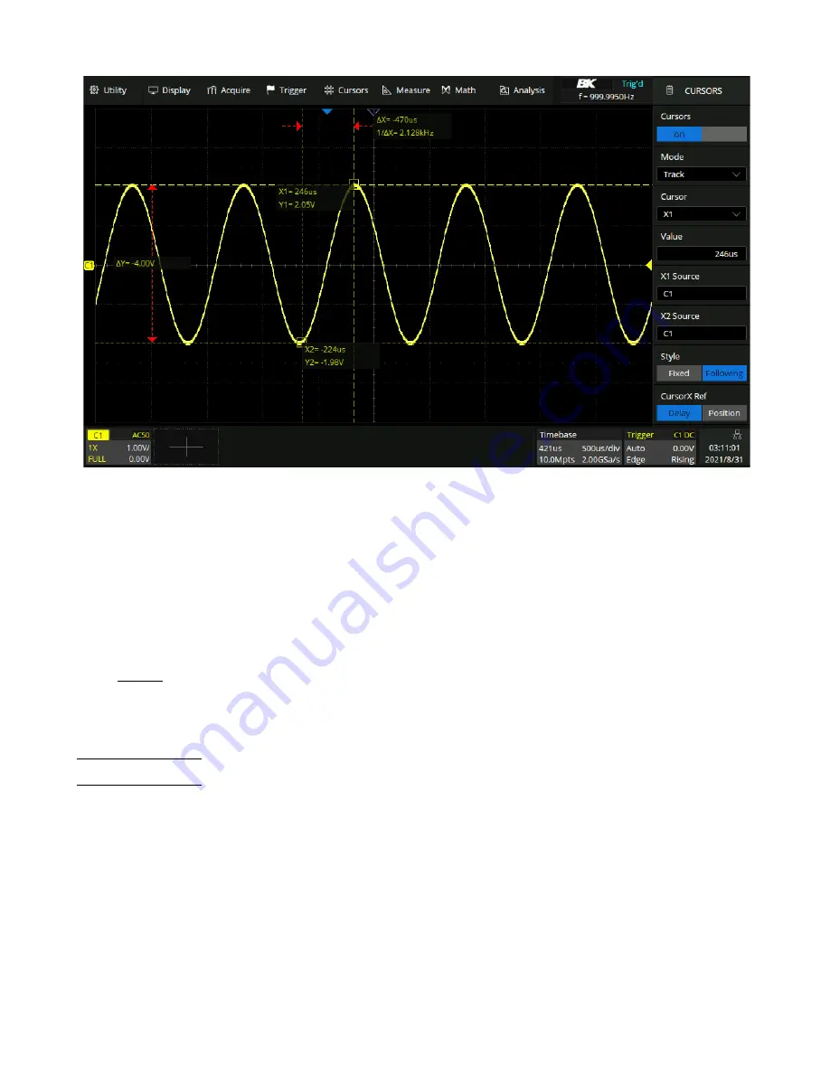
Cursors
129
Figure 11.2
Track Cursor Mode
–
Measure
: When measurements are displayed, this mode shows the cursor locations used to make the measurement.
When you add a measurement, it becomes the one that cursors are displayed for. The measurement whose cursor
locations are displayed is selected in the
Measure Item
option. Figure
demonstrates measure mode with
cursors measuring width.
11.1
X Cursors
X cursors are vertical dashed lines that adjust horizontally and can be used to measure time (when the source is FFT
waveform, X cursors measure frequency).
X1 cursor is the left (default position) vertical dotted line; it can be moved to any place of the screen.
X2 cursor is the right (default position) vertical dotted line; it can be moved to any place of the screen.
Use the
Universal Knob
to set the X1 and X2 cursor values. The values are displayed in the cursors box along with the
difference between X1 and X2 (T) and 1/T. (See figure
When cursor type is set to X2-X1, use
Universal Knob
to move the X1 and X2 cursors together. The value under the
menu option is the difference between the X1 and X2 cursors.
Содержание 2560B Series
Страница 1: ......
Страница 51: ...Digital Channels 51 Figure 8 9 Digital Bus...
Страница 127: ...Serial Trigger and Decode 127 Figure 10 63 Manchester Bus...
Страница 168: ...Reference Waveform 168 Figure 14 1 Recall REFB...
Страница 210: ...Save Recall 210 Figure 22 4 Save As...


