


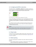


Fig. 10: Connection terminal
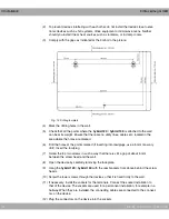
Plastic cable fixes are included for fixing the connecting cable. However, you should ensure
the installation cable cannot be pulled out by placing cable clips [D] in front of the device.
The wires [B] in the connecting cable [A] should protrude about 100 mm from the cable
sheath. The length of cable sheath [C] from the cable clips should be around 80 mm. The
insulation on the ends of the wires should be stripped back by about 6-7 mm.
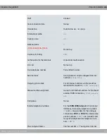
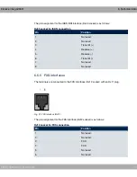
Connection terminal
Name
Telephone numbers
Terminal 1
FXS1 and FXS2
and
Terminal 2
FXS3 and FXS4
and
Terminal 3 (hybird 130 only) FXS 5 and FXS 6
Terminal 4
Switch contact
Terminal 5
ISDN 1 (configurable)
0
Terminal 6
ISDN 2 (configurable)
#$
Terminal 7 (hybird 130 only) Up0
bintec elmeg GmbH
3 Installation
elmeg hybird 120 / hybird 130
29
Содержание elmeg hybird 120
Страница 18: ...Table of Contents bintec elmeg GmbH xvi elmeg hybird 120 hybird 130...
Страница 48: ...Fig 11 Cable fix Fig 12 Strip the insulation 3 Installation bintec elmeg GmbH 30 elmeg hybird 120 hybird 130...
Страница 65: ...6 6 WEEE information bintec elmeg GmbH 6 Technical data elmeg hybird 120 hybird 130 47...
Страница 172: ...Fig 67 VoIP Settings SIP Provider New 13 VoIP bintec elmeg GmbH 154 elmeg hybird 120 hybird 130...


