


12.3. Motor connection
Connect the motor cable to the U, V, W and PE terminals.
The inverter will be deactivated in the event of a short circuit at the terminals U, V, W.
We recommend PTC evaluation using commercially available devices to achieve effective protection
of the motor.
If interrupting contacts (e.g. contactors or motor protection switches etc.) have to be installed between
the motor and inverter, the circuit must be configured so as to ensure that the ENABLE signal (terminals
10/11) is deactivated before separation of the inverter/motor connection. A relay switching time of
approx. 30 ms suffices.
Long motor cables (> 20m) in connection with high voltage peaks caused by the fast switching output
stages of the inverter may endanger the motor insulation. In such cases we recommend to use suitable
filter measures (e.g. motor chokes or dU/dt filters) to protect the motor.
12.4. Interference suppression measures / EMC
(electromagnetic compatibility)
12.4.1. General information
Inverters are electronic devices which are used in industrial and commercial systems. In accordance
with the EMC-directives 89/336/EEC the inverters are not designed for independent operation. Thus
inverters should be used for further processing through competent machine/system manufacturers.
By this, the devices do not require a CE-marking. The proof of the conformity of the machine/ system
with the required EMC-directives must be furnished by the manufacturer or operator of the system.
The inverters of the ACM series are equipped with an internal filter and designed to be used in class
"A" environments (first environment, restricted distribution) according to the product standard EN
61800-3.
The evaluation of the conformity took place in a practical structure having taken into account the
following installation notes.
Voltage peaks produced by other devices connected at the mains supply can possibly disturb or even
damage the inverter. Input chokes (option) can be used to protect the inverter against these voltage
peaks (caused e.g. by switching off of high loads from the mains).
12.4.2. Installation notes
During operation, electrical/electronic devices can influence or disturb each other via power supply or
other metallic connections.
The electromagnetic compatibility of the system is highly influenced by the manner of the installation.
Measures for the grounding, shielding and filtering are to be particularly considered. By paying attention
to the following installation notes it can be assumed that the EMC limit values for the system/machine
are kept.
•
Inverters and optional components like input or output chokes must be in metal-to-metal contact
with the grounded mounting plate using the whole surface if possible. Use preferably galvanized
mounting plates. Painted mounting surfaces must be free from paint.
•
Lay the mains, motor and control cables in large distance from each other.
•
Use shielded motor cables connected to earth on both sides.
•
Connect the motor cable shield with the PE terminal located in the terminal box of the motor. Use
possibly metallic cable glands.
•
Optional output chokes must be mounted close to the inverter and connected with shielded cables.
Connect the cable shield to earth on both sides.
•
Use shielded control cables connected to earth on both sides.
•
Unshielded control cables must be twisted.
•
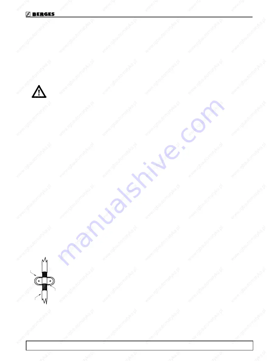
Connect the cable shields either with the mounting plate using ground clamps and contacted over
as large an area or at an equipotential bar (see picture).
•
Use a central earthing point for the whole machine/system (mounting plate). Connect this point to
earth using earth cables with a large cross section or flat copper braids.
R
e
move any
p
a
in
t
o
r va
rn
ish
!
Mo
to
r ca
b
le
w
ith
br
a
ide
d
s
hiel
d
.
L
a
rg
e-
ar
e
a
c
o
n
tac
ti
n
g
of
t
h
e
c
a
ble
s
h
ield
.
BERGES electronic
09.07.2001 Operating manual ACM D2/S2 17
Содержание ACM S2
Страница 1: ...Operating manual ACM D2 S2 ...
Страница 2: ......
Страница 28: ...15 Programming ACM D2 S2 15 1 Program structure BERGES electronic 26 Operating manual ACM D2 S2 09 07 2001 ...
Страница 29: ...BERGES electronic 09 07 2001 Operating manual ACM D2 S2 27 ...
Страница 60: ...20 Notes BERGES electronic 58 Operating manual ACM D2 S2 09 07 2001 ...
Страница 61: ...BERGES electronic ...
Страница 62: ...BERGES electronic ...
Страница 63: ......