


Programming Commander Pro
Operating Instructions 1280-7/1281-7 - 00.0 - 01/2023
103
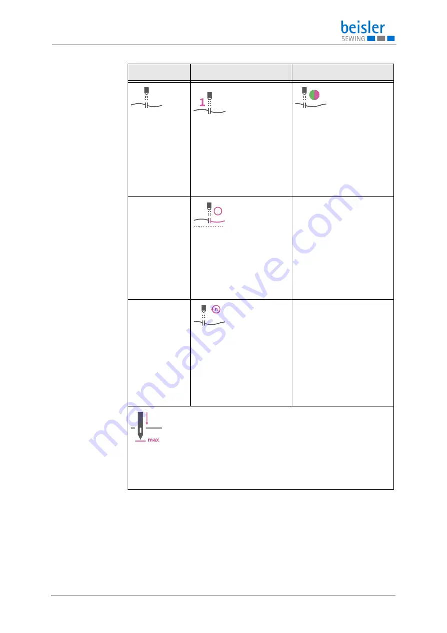
1.3.5
Thread monitor
The thread monitor
is used to detect
thread breakage
1.3.5.1
Thread monitor
The thread monitor detects
a thread breakage and stops
the sewing process.
Value range: ON/OFF
1.3.5.2
Thread monitor
sensitivity
Thread monitor sensitivity is
used to adjust to different yarns /
colors to detect faulty material.
Default: 50
Value range: 0-100
1.3.5.4
Seam length until thread
monitor info active
Seam length until thread monitor
info is activated to avoid faulty
detection at the beginning of the
seam, which can be caused by
thread loops.
Default: 2.0
Value range: 0.0 - 10.0 cm
1.3.5.
Sewing speed with thread
monitor activated
Sewing speed when the thread
monitor is activated. When the
thread monitor is activated, a
certain sewing speed can be set
from which the thread monitor is
active.
Default: 3000 rpm
Value range: 100-5500 rpm
1.3.6
Needle position at bottom dead center
This refers to the needle position at the bottom dead center.
Default: 180°
Value range: 0-360°
Selection
Setting 1
Setting 2
Содержание 1280-7
Страница 1: ...1280 7 1281 7 Operating Instructions ...
Страница 200: ...Decommissioning 198 Operating Instructions 1280 7 1281 7 00 0 01 2023 ...
Страница 202: ...Disposal 200 Operating Instructions 1280 7 1281 7 00 0 01 2023 ...
Страница 213: ......