Manual 2100-419E
Page
35 of 48
OPEN LOOP
(Well System Applications)
WATER CONNECTIONS
It is very important that an adequate supply of clean,
noncorrosive water at the proper pressure be provided
before the installation is made. Insufficient water, in
the heating mode for example, will cause the low
pressure switch to trip, shutting down the heat pump. In
assessing the capacity of the water system, it is
advisable that the complete water system be evaluated
to prevent possible lack of water or water pressure at
various household fixtures whenever the heat pump
turns on. All plumbing to and from the unit is to be
installed in accordance with local plumbing codes. The
use of plastic pipe, where permissible, is recommended
to prevent electrolytic corrosion of the water pipe.
Because of the relatively cold temperatures encountered
with well water, it is strongly recommended that the
water lines connecting the unit be insulated to prevent
water droplets form condensing on the pipe surface.
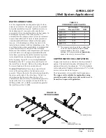
Refer to piping, Figure 24. Slow closing
Solenoid
Valve
(6)
with a 24 V coil provides on/off control of
the water flow to the unit. Refer to the wiring diagram
for correct hookup of the valve solenoid coil.
Constant Flow Valve (7)
provides correct flow of
water to the unit regardless of variations in water
pressure. Observe the water flow direction indicated by
the arrow on the side of the valve body. Table 8 is a
table showing the flow rate of each valve. Two
constant flow rate valves may be installed in parallel to
increase the flow. For example, when a 8603-007 (6
GPM) and 8603-011 (5 GPM) are installed in parallel
the total flow will be 11 GPM.
FIGURE 24
PIPING DIAGRAM
MIS-1569
TO WATER COIL
FROM WATER COIL
COPPER WATER COIL LIMITATIONS
Copper water coils are available as a factory installed
option. The unit model number will indicate the coil
option as the next to last character; “X” is for standard
coil constructed of Cupronickel material and “4” is from
a water coil constructed of copper.
The Cupronickel coil is suitable for all applications.
The copper coil is suitable for applications using
ground loop and cooling tower only and is never to
be used in an open well application.
TABLE 8
CONSTANT FLOW VALVES
1
The pressure drop through the constant flow
valve will vary depending on the available
pressure ahead of the valve. Unless
minimum of 15 psig is available immediately
ahead of the valve, no water will flow.
.
o
N
t
r
a
P
e
l
b
a
l
i
a
v
A
.
n
i
M
G
I
S
P
e
r
u
s
s
e
r
P
e
t
a
R
w
o
l
F
M
P
G
7
0
0
-
3
0
6
8
5
1
1
6
8
0
0
-
3
0
6
8
5
1
1
8
0
1
0
-
3
0
6
8
5
1
1
4
1
1
0
-
3
0
6
8
5
1
1
5
9
1
0
-
3
0
6
8
5
1
1
3
Содержание QW242
Страница 6: ...Manual 2100 419E Page 6 of 48 FIGURE 1 UNIT DIMENSIONS ...
Страница 9: ...Manual 2100 419E Page 9 of 48 FIGURE 4 INSTALLATION OF UNIT THROUGH WALL WITH WALL SLEEVE MIS 1564 ...
Страница 21: ...Manual 2100 419E Page 21 of 48 FIGURE 15 REMOTE THERMOSTAT WIRING DIAGRAM X OPTION ...
Страница 22: ...Manual 2100 419E Page 22 of 48 FIGURE 16 REMOTE THERMOSTAT WIRING DIAGRAM A THERMOSTAT OPTION 4102 021A ...
Страница 23: ...Manual 2100 419E Page 23 of 48 4102 022C FIGURE 17 REMOTE THERMOSTAT WIRING DIAGRAM D THERMOSTAT OPTION ...
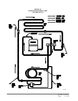
Страница 41: ...Manual 2100 419E Page 41 of 48 FIGURE 27 WATER SOURCE HEAT PUMP COOLING CYCLE MIS 329 ...
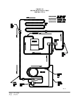
Страница 42: ...Manual 2100 419E Page 42 of 48 FIGURE 28 WATER SOURCE HEAT PUMP HEATING CYCLE MIS 328 ...


