Manual 2100-419E
Page
46 of 48
H
eat
G
en
.
Pow
er Fa
ilu
re
Blow
n Fus
e or T
ripped B
reak
er
Faulty
Wir
ing
Loose T
erm
inals
Low V
oltage
De
fectiv
e Contac
ts in C
ontactor
Co
mp
re
ss
or O
ver
load
Po
tent
ial Re
lay
Run C
apacitor
Star
t Capac
itor
Faulty
Wir
ing
Loose T
erm
inals
Contr
ol Trans
form
er
Low V
oltage
Ther
mos
tat
Contac
tor C
oil
Pres
sur
e Contr
ols (
High or
Low)
Indoor B
low
er R
elay
Dis
char
ge Line Hitting Ins
ide of S
hell
Bear
ings D
efec
tiv
e
Seiz
ed
Va
lve De
fe
ctive
Motor
Wingings
Defec
tiv
e
Refr
igerant C
harge Low
Re
friger
ant Ov
erc
harge
High H
ead Pres
sur
e
Low H
ead Pres
sur
e
High S
uc
tion P
res
su
re
Low S
uction P
res
sur
e
Non-
Condens
ables
Unequaliz
ed Pres
su
re
s
So
lenoid Va
lve S
tuc
k C
los
ed (H
tg)
So
lenoid Va
lve S
tuc
k C
los
ed (C
lg)
Solenoid V
alve S
tuc
k O
pen (H
tg or C
lg)
Leaking
De
fectiv
e Va
lve or
Co
il
Plugged or
Re
str
ic
ted M
eter
ing D
ev
ic
e (
Htg)
Sc
aled or P
lugged C
oil (
Htg)
Sc
aled or P
lugged C
oil (
CLg)
Wa
ter V
olu
me
Low (
Htg)
Wa
ter V
olu
me
Low (
Clg
)
Low W
ater
Te
mper
ature (
Htg)
Plugged or
Res
tri
cted M
etering D
evic
e (C
lg)
Fins
Dir
ty
or P
lugged
Mo
tor W
inding D
efec
tiv
e
Air Vo
lu
me
Lo
w
Air Fi
lte
rs
Dirt
y
Under
siz
ed or R
estr
ic
ted D
uctw
ork
Au
xillary
Heat
Up
stream of
Co
il
C
o
mpr
e
sso
r W
ill N
o
t R
u
n
N
o
P
o
w
e
r at C
onta
c
tor
C
o
mpr
e
sso
r W
ill N
o
t R
u
n
P
o
w
e
r at C
onta
c
tor
C
o
m
p
re
s
s
o
r "
H
um
s
"
B
u
t
W
ill N
o
t S
tar
t
C
o
m
pr
es
s
o
r C
y
c
le
s
on O
v
e
rload
Ther
m
o
s
ta
t C
h
ec
k
Li
ght
Lite-
L
oc
k
ou
t R
e
lay
C
o
m
p
re
s
s
o
r O
ff on
H
igh
P
re
s
s
u
re
C
o
n
tro
l
C
o
m
p
re
s
s
o
r O
ff on
Low
P
re
s
s
u
re
C
o
n
tro
l
C
o
m
p
re
s
s
o
r N
o
is
y
H
e
ad P
res
s
u
re T
oo H
ig
h
H
e
ad P
res
s
u
re T
oo L
ow
S
u
c
tion P
res
s
ur
e T
o
o H
igh
S
u
c
tion P
res
s
ur
e T
o
o Low
I.
D
. B
low
e
r W
ill N
o
t S
tar
t
I.D
. C
o
il Fr
os
ti
n
g
or
Ic
in
g
H
igh C
om
pr
es
s
or
A
m
ps
E
x
ce
ssiv
e
W
a
te
r
U
s
a
g
e
C
o
m
p
re
s
s
o
r R
u
ns
C
onti
nuou
s
ly
– N
o
C
oolin
g
Liqu
id R
efr
ig
er
ant F
lo
odin
g B
ac
k
To
C
o
m
p
re
s
s
o
r
C
o
m
p
re
s
s
o
r R
u
ns
C
onti
nuou
s
ly
– N
o
H
eating
R
e
v
er
s
ing V
al
v
e D
oe
s
N
o
t S
h
ift
Liqu
id R
efr
ig
er
ant F
lo
odin
g B
ac
k
To
C
o
m
p
re
s
s
o
r
A
u
x
. H
e
a
t on I.D
. B
low
er
O
ff
E
x
ce
ssiv
e
Op
e
ra
tio
n
C
o
st
s
Ic
e i
n
W
a
ter
C
o
il
Heati
ng Cy
cle
AUX
.
Cooling
Cycle
Heati
ng or C
ooling C
yc
les
In
d
oor
Bl
ow
e
r
M
otor
a
nd C
o
il
INDO
O
R
S
E
CT
IO
N
PO
W
ER
SU
PP
L
Y
W
at
er
S
o
le
noid
R
ev.
V
a
lv
e
W
at
e
r C
o
il
W
AT
E
R CO
IL
S
E
C
T
IO
N
Line
V
o
lta
g
e
C
ontr
ol C
ir
c
uit
C
ompr
e
s
s
o
r
R
e
fr
ig
e
ra
nt S
y
s
te
m
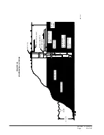
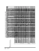
QUICK REFERENCE TROUBLESHOOTING CHART FOR WATER TO AIR HEAT PUMP
DENOTES COMMON CAUSE
DENOTES OCCASIONAL CAUSE
Содержание QW242
Страница 6: ...Manual 2100 419E Page 6 of 48 FIGURE 1 UNIT DIMENSIONS ...
Страница 9: ...Manual 2100 419E Page 9 of 48 FIGURE 4 INSTALLATION OF UNIT THROUGH WALL WITH WALL SLEEVE MIS 1564 ...
Страница 21: ...Manual 2100 419E Page 21 of 48 FIGURE 15 REMOTE THERMOSTAT WIRING DIAGRAM X OPTION ...
Страница 22: ...Manual 2100 419E Page 22 of 48 FIGURE 16 REMOTE THERMOSTAT WIRING DIAGRAM A THERMOSTAT OPTION 4102 021A ...
Страница 23: ...Manual 2100 419E Page 23 of 48 4102 022C FIGURE 17 REMOTE THERMOSTAT WIRING DIAGRAM D THERMOSTAT OPTION ...
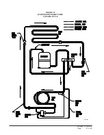
Страница 41: ...Manual 2100 419E Page 41 of 48 FIGURE 27 WATER SOURCE HEAT PUMP COOLING CYCLE MIS 329 ...
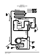
Страница 42: ...Manual 2100 419E Page 42 of 48 FIGURE 28 WATER SOURCE HEAT PUMP HEATING CYCLE MIS 328 ...


