background image

Manual 2100-419E
Page

28 of 48

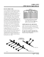
WATER LINES

WALL BRACKET

WALL BRACKET

TOP VIEW

WALL LOCATION

4"

FLUID ACCESS FROM FLOOR

FLOOR

WALL BRACKET
(LEFT BRACKET 
REMOVED FOR
CLARITY)

FLUID ACCESS
FROM TOP

OPENING IN
REAR OF UNIT
3" x 8"

BACK OF UNIT

MIS-1601
11/10/00

8 1/2"

63 1/2"

23 1/2"

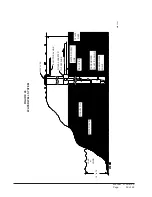
FIGURE  19

FLUID CONNECTIONS ON UNIT WITHOUT VENTILATION WALL SLEEVE

MIS-1601

Содержание QW242

Страница 1: ...UCTIONS Models QW242 QW302 QW361 QW421 QW481 QW601 Copyright 2004 Manual No 2100 419E Supersedes 2100 419D File Vol II Tab 14 Date 02 10 06 Bard Manufacturing Company Bryan Ohio 43506 Since 1914 Moving ahead just as planned Earth Loop Fluid Temperatures 25 110 Ground Water Temperature 45 75 ...

Страница 2: ... Adjustments 24 Optional CFM 25 Important Installer Note 25 Phase Monitor 25 Service Hints 25 Sequence of Operation 25 Pressure Service Ports 26 Pressure Tables 29 30 Optional Accessories 31 Closed Loop Earth Coupled Ground Loop Applications Circulation System Design 32 Copper Water Coil Application 32 Start Up Procedure for Closed Loop System 33 Open Loop Well System Applications Water Connection...

Страница 3: ...iring X Option 21 Figure 16 Remote Thermostat Wiring A Option 22 Figure 17 Remote Thermostat Wiring D Option 23 Figure 18 Fluid Connections w Ventilation Wall Sleeve 27 Figure 19 Fluid Connections w o Ventilation Wall Sleeve 28 Figure 20 Circulation System 32 Figure 21 Water Temperature and Pressure Test Procedure 33 Figure 22 Performance Model WGPM 1C 34 Figure 23 Performance Model WGPM 2C 34 Fig...

Страница 4: ...Procedures for Ground Source IGSHPA Heat Pump Systems Soil and Rock Classification for the Design IGSHPA of Ground Coupled Heat Pump Systems Ground Source Installation Standards IGSHPA Closed Loop Geothermal Systems Slinky IGSHPA Installation Guide FOR MORE INFORMATION CONTACT THESE PUBLISHERS ACCA Air Conditioning Contractors of America 1712 New Hampshire Avenue Washington DC 20009 Telephone 202 ...

Страница 5: ...andard High Pressure Switch Low Pressure Switch Compressor Time Delay CLIMATE CONTROL OPTIONS X None A Electronic Non Prog Man Auto D Electronic Prog Man Auto COLOR OPTIONS V Platinum w Slate Front Vinyl 4 Gray Painted QW 36 1 A 0Z B X V X X X COIL OPTIONS X Standard Cupronickel Water Coil 4 Copper Water Coil TABLE 1 ELECTRICALSPECIFICATIONS L E D O M D E T A R S T L O V E S A H P T I U C R I C E ...

Страница 6: ...Manual 2100 419E Page 6 of 48 FIGURE 1 UNIT DIMENSIONS ...

Страница 7: ...a 36 doorway If the door height allows the unit can be slid sideways through the door If the unit can not be slid through the door then the unit will have to be put on a cart and tipped down to roll through the door It is recommended that an appliance cart by used with a strap to hold the unit on the cart The wheels of the unit must be locked If the wheels were allowed to roll the unit could roll ...

Страница 8: ... tags and or labels attached to the equipment While these instructions are intended as a general recommended guide they do not supersede any national and or local codes in any way Authorities having jurisdiction should be consulted before the installation is made See Page 4 for information on codes and standards Size of unit for a proposed installation should be based on heat loss calculation made...

Страница 9: ...Manual 2100 419E Page 9 of 48 FIGURE 4 INSTALLATION OF UNIT THROUGH WALL WITH WALL SLEEVE MIS 1564 ...

Страница 10: ...Manual 2100 419E Page 10 of 48 FIGURE 6 DUCTEDAPPLICATION MIS 1558 FIGURE 5 INSTALLATION WITH FREE BLOW PLENUM CEILING FLOOR DUCT FLANGE DUCT FIXED CEILING SUSPENDED CEILING FLOOR MIS 1559 20 IN MINIMUM ...

Страница 11: ...he ceiling This extends 20 above the unit for a total height above the floor of 10 7 8 The unit is equipped with a variable speed indoor blower motor which increases in speed with an increase in duct static pressure The unit will therefore deliver proper rated air flow up to the Maximum ESP shown in Table 5 However for quiet operation of the air system the duct static should be kept as low as prac...

Страница 12: ...equires a water trap for proper drainage See Figure 8A The drain can be routed through the floor or through the wall If the drain is to be routed through an unconditioned space it must be protected from freezing The drain line must be able to be removed from the unit if it is necessary to remove the unit from the wall MIS 1568 MIS 976 MIS 974 ...

Страница 13: ...ps necessary to remove each of the vent options are listed following It is recommended that the mist eliminator be inspected annually and serviced as required The mist eliminator can be inspected from the outside of the building by looking through the outdoor grille The mist eliminator can be serviced from the outside The outdoor grille must be removed to do so WALL MAXIMUM 10 FOR REAR DRAIN DRAIN...

Страница 14: ...to the mist eliminator 1 The two mounting screws in the front of the CRV must be removed 2 The power connectors for the CRV located on the right side of the unit must be disconnected Squeeze the tabs on the sides of the connector and pull straight out Unplug both of the connectors 3 Slide the CRV straight out of the unit The mist eliminator can be seen through the opening in the back of the unit T...

Страница 15: ...RY VENTILATOR 3 Underneath the heat recovery cassette there is a power connector for the lower blower assembly To disconnect this plug the tabs on both sides of the plug must be squeezed to release the plug While squeezing the tabs pull the plug out of the socket 4 The QERV is plugged into the unit on the right side of the unit Both of these plugs must be disconnected to remove the QERV Squeeze th...

Страница 16: ...piping connections are to be within the confines of this bracket See Figure 1 for cabinet openings and location of fluid coil connection points 2 Position the unit in front of the wall mounting bracket 3 Remove the locking screws from the wheels Refer to Figure 11 4 Roll the unit up to the wall mounting bracket The unit must be level from side to side If any adjustments are necessary shim up under...

Страница 17: ...age 17 of 48 FIGURE 12 UNIT MOUNTING WITHOUT VENTILATION WALL SLEEVE REFER TO MOUNTING INSTRUCTIONS ON PAGE 16 SIDE TRIM 2 PIECES SIDE TRIM 2 PIECES WALL MOUNTING BRACKET BOTTOM TRIM EXTENSION BOTTOM TRIM PIECE MIS 1557 ...

Страница 18: ...Manual 2100 419E Page 18 of 48 FIGURE 13 COMPONENTLOCATION SIDE FIELD WIRE ENTRANCE REMOTE THERMOSTAT TERMINAL BLOCK INDOOR BLOWER CONTROL BOX CIRCUIT BREAKER PANEL ELECTRICAL CONNECTION PANEL MIS 1556 ...

Страница 19: ...08V operation reconnect from 240V to 208V tap The acceptable operating voltage range for the 240 and 208V taps are as noted in Table 2 The standard Climate Control Option X is a remote thermostat connection terminal block See Figure 17 for wiring diagram Compatible thermostats are listed in Table 3 The Climate Control Option A is an electronic non programmable manual or auto changeover thermostat ...

Страница 20: ... or pin 11 of P2 is 24 VAC grounded L terminal or pin 12 of P2 is compressor lockout output This terminal is activated on a high or low pressure trip by the compressor control module This is a 24 VAC output W2 terminal or pin 9 of P2 is second stage heat if equipped If the unit is equipped with an optional hot water coil plenum box the water valve will be connected to this terminal O1 terminal of ...

Страница 21: ...Manual 2100 419E Page 21 of 48 FIGURE 15 REMOTE THERMOSTAT WIRING DIAGRAM X OPTION ...

Страница 22: ...Manual 2100 419E Page 22 of 48 FIGURE 16 REMOTE THERMOSTAT WIRING DIAGRAM A THERMOSTAT OPTION 4102 021A ...

Страница 23: ...Manual 2100 419E Page 23 of 48 4102 022C FIGURE 17 REMOTE THERMOSTAT WIRING DIAGRAM D THERMOSTAT OPTION ...

Страница 24: ... PRESSURE SWITCH AND LOCKOUT SEQUENCE If the high pressure switch opens the compressor contactor will de energize immediately The lockout timer will go into a soft lockout and stay in soft lockout until the high pressure switch closes and the delay on break time has expired If the high pressure switch opens again in the same operating cycle the unit will go into manual lockout condition and the al...

Страница 25: ...n LED will light and contactor will energize If phases are reversed the red fault LED will be lit and compressor operation is inhibited If a fault condition occurs reverse two of the supply leads to the unit Do not reverse any of the unit factory wires as damage may occur SERVICE HINTS 1 Caution user to maintain clean air filters at all times Also not to needlessly close off supply air registers T...

Страница 26: ...8 0 0 0 2 1 0 0 0 1 0 0 0 1 5 7 1 1 1 8 4 W Q 0 0 8 0 0 0 4 1 0 0 1 1 0 0 1 1 5 7 1 1 1 0 6 W Q 0 0 8 0 0 5 5 1 0 5 2 1 0 5 2 1 0 0 4 1 HEATING A 24V solenoid coil on reversing valve controls heating cycle operation Two thermostat options one allowing Auto change over from cycle to cycle and the other constantly energizing solenoid coil during heating season and thus eliminating pressure equalizat...

Страница 27: ...L SLEEVE MIS 1602 1 18 01 REF 23 1 2 63 1 2 8 1 2 33 SIDE TRIM PIECES SHIPPED WITH UNIT IF THE WALL THICKNESS IS LESS THAN 14 BUT GREATER THAN 8 A SIDE TRIM EXTENSION KIT QSTX42 IS REQUIRED REFER TO UNIT SPEC SHEET FOR PROPER COLOR SIDE TRIM PEICES SHIPPED WITH UNIT FLUID ACCESS FROM CEILING FLUID ACCESS FROM CEILING 8 TO 14 EXTERIOR WALL SLEEVE TOP OF UNIT FIGURE 18 FLUID CONNECTIONS ON UNIT WITH...

Страница 28: ...IEW WALL LOCATION 4 FLUID ACCESS FROM FLOOR FLOOR WALL BRACKET LEFT BRACKET REMOVED FOR CLARITY FLUID ACCESS FROM TOP OPENING IN REAR OF UNIT 3 x 8 BACK OF UNIT MIS 1601 11 10 00 8 1 2 63 1 2 23 1 2 FIGURE 19 FLUID CONNECTIONS ON UNIT WITHOUT VENTILATION WALL SLEEVE MIS 1601 ...

Страница 29: ... 2 3 7 4 3 2 3 7 1 5 2 4 7 7 6 2 4 7 5 8 2 5 7 2 0 3 7 6 0 8 e d i S w o L e d i S h g i H 2 7 2 2 1 3 7 2 3 1 4 7 4 4 1 4 7 5 5 1 5 7 8 6 1 6 7 1 8 1 6 7 5 9 1 7 7 9 0 2 7 7 5 2 2 8 7 0 4 2 8 7 7 5 2 9 7 4 7 2 9 7 2 9 2 0 8 0 1 3 2 7 5 8 e d i S w o L e d i S h g i H 6 7 6 2 1 6 7 7 3 1 7 7 9 4 1 7 7 0 6 1 8 7 4 7 1 9 7 7 8 1 9 7 2 0 2 0 8 6 1 2 0 8 3 3 2 1 8 8 4 2 1 8 6 6 2 2 8 4 8 2 2 8 2 0 3 3...

Страница 30: ... 2 8 8 7 3 2 7 9 5 4 2 1 2 4 W Q 8 6 e d i S w o L e d i S h g i H 3 3 4 7 1 7 3 9 7 1 1 4 5 8 1 5 4 2 9 1 0 5 8 9 1 5 5 5 0 2 0 6 2 1 2 5 6 9 1 2 1 7 6 2 2 7 7 4 3 2 4 8 1 4 2 0 9 9 4 2 1 8 4 W Q 8 6 e d i S w o L e d i S h g i H 1 3 6 7 1 5 3 1 8 1 9 3 7 8 1 3 4 4 9 1 7 4 0 0 2 2 5 7 0 2 6 5 5 1 2 2 6 2 2 2 7 6 0 3 2 3 7 8 3 2 9 7 7 4 2 5 8 6 5 2 1 0 6 W Q 8 6 e d i S w o L e d i S h g i H 3 3 4...

Страница 31: ...or is matched to the QW model that they will be used with Side Trim Extension Kits Required when wall thickness is less than 14 inches and works for walls down to 8 inches thick Used in place of standard trim kit supplied with unit to cover the space between unit and wall Unit Compatibility QSTX42A V Platinum vinyl QSTX42 A4 Gray paint All Models Free Blow Plenum Boxes Unit Compatibility QPB42 V P...

Страница 32: ... the performance of the circulator must be closely matched with the FIGURE 20 CIRCULATION SYSTEM pressure of head loss of the entire system in order to provide the required flow through the heat pump Insufficient flow through the heat exchanger is one of the most common causes of system failure Proper system piping design and circulator selection will eliminate this problem Bard supplies a work sh...

Страница 33: ...ule model for sufficient capacity If the module selection is correct there is probably trapped air or a restriction in the piping circuit 8 Start the unit in cooling mode By moving the thermostat switch to cool fan should be set for AUTO 9 Check the system refrigerant pressures against the cooling refrigerant pressure table in the installation manual for rated water flow and entering water tempera...

Страница 34: ...0 10 20 30 40 50 60 70 0 5 10 15 20 25 30 35 Flow GPM Head Feet FIGURE 23 PERFORMANCE MODEL WGPM 2C LOOP PUMP MODULE 0 5 10 15 20 25 30 35 0 5 10 15 20 25 30 35 Flow GPM Head Feet FIGURE 22 PERFORMANCE MODEL WGPM 1C LOOP PUMP MODULE ...

Страница 35: ...Flow Valve 7 provides correct flow of water to the unit regardless of variations in water pressure Observe the water flow direction indicated by the arrow on the side of the valve body Table 8 is a table showing the flow rate of each valve Two constant flow rate valves may be installed in parallel to increase the flow For example when a 8603 007 6 GPM and 8603 011 5 GPM are installed in parallel t...

Страница 36: ...e well pump must be sized in such a way that three requirements are met 1 Adequate flow rate in GPM 2 Adequate pressure at the fixture 3 Able to meet the above from the depth of the well feet of lift The pressure requirements put on the pump are directly affected by the diameter of pipe being used as well as by the water flow rate through the pipe The work sheet included in manual 2110 078 should ...

Страница 37: ... suspended particles in the water is that it will erode metal parts pumps heat transfer coils etc So long as the filter is cleaned and periodically maintained suspended particles should pose no serious problem Consult with your well driller 3 Corrosion of Metal Corrosion of metal parts results from either highly corrosive water acid water generally not the case with ground water of galvanic reacti...

Страница 38: ...sible pump suspended in the dry well casing Jet pumps and other types of suction pumps normally consume more electrical energy than similarly sized submersible pumps Pipe the unit the same as a water well system D Size the pump to provide necessary GPM for the ground water heat pump A 12 GPM or greater water flow rate is required on all modes when used on this type system E A pressure tank should ...

Страница 39: ... 48 FIGURE 26 WATER WELL SYSTEM 12 to 15 LAKE or POND WATER LEVEL GRAVEL FILL WELL CAP ELECTRICAL LINE PITLESS ADAPTER TO PRESSURE TANK SUBMERSIBLE PUMP PERFORATED PLASTIC CASING DROP PIPE WATER SUPPLY LINE 15 to 20 DEEP MIS 1607 ...

Страница 40: ...rature ports are recommended in both supply and return lines for system flow balancing Water flow can be accurately set by measuring the refrigerant to water heat exchangers water side pressure drop See Table 9 for water flow and pressure drop information WARNING Thin ice may result in the vicinity of the discharge line For complete information on water well systems and lake and pond applications ...

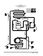
Страница 41: ...Manual 2100 419E Page 41 of 48 FIGURE 27 WATER SOURCE HEAT PUMP COOLING CYCLE MIS 329 ...

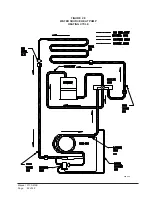
Страница 42: ...Manual 2100 419E Page 42 of 48 FIGURE 28 WATER SOURCE HEAT PUMP HEATING CYCLE MIS 328 ...

Страница 43: ...ing pressure equalization through the compressor This may leave low side shell and suction line tubing pressurized If the brazing torch is then applied to the low side while the low side shell and suction line contains pressure the pressurized refrigerant and oil mixture could ignite when it escapes and contacts the brazing flame To prevent this occurrence it is important to check both the high an...

Страница 44: ... u d e R e r u t s i o M f o e c n e d i v E d n a d e r u c c o s a h n o i t c n u f l a m f o e r u l i a f r o t o M t n e s e r p s i e r u t s i o m m r o f r e p d n a r o t o m e c a l p e R k c e h C e r u t s i o M r e v o m r i a e d i s n i t n e s e r p e r u t s i o m f o e c n e d i v E k c e h C e r u t s i o M m r o f r e P O D T N O D s n o i t c e n n o c d n a g n i r i w s l o...

Страница 45: ...i w s c a i r T r o f k c e h C y a l e r N O T P M Y S E R U D E C O R P E S U A C e s i o n e v i s s e c x E e s i o n r o t o m r o t c u d t e n i b a c e s i o n r i a s i t i f i e n i m r e t e D y r s s e c e n f i r e m o t s u c w e i v r e t n I e s i o N r i A d e e p s r e w o l b h g i h g n i t a e r c c i t a t s h g i H y l r e p o r p t e s w o l f r i a s I n w o d w o l s o t ...

Страница 46: ... Defective Air Volume Low Air Filters Dirty Undersized or Restricted Ductwork Auxillary Heat Upstream of Coil Compressor Will Not Run No Power at Contactor Compressor Will Not Run Power at Contactor Compressor Hums But Will Not Start Compressor Cycles on Overload Thermostat Check Light Lite Lockout Relay Compressor Off on High Pressure Control Compressor Off on Low Pressure Control Compressor Nois...

Страница 47: ...talled 5 User s Owner s Name Address 6 Unit Location WATER SYSTEM INFORMATION 7 Open Loop System Water Well Closed Loop System A If Open Loop where is water discharged 8 The following questions are for Closed Loop systems only A Closed loop system designed by B Type of antifreeze used Solution C System type Series Parallel D Pipe Material Nominal Size E Pipe Installed 1 Horizontal Total length of ...

Страница 48: ...contactor A 19 Amperage at compressor common terminal A 20 Suction line temperature 6 from compressor F 21 Superheat at compressor F 22 Liquid line temperature at metering device F 23 Coil subcooling F INDOOR SIDE DATA Cooling Heating 24 Dry bulb temperature at air entering indoor coil F 25 Wet bulb temperature of air entering indoor coil F 26 Dry bulb temperature of air leaving indoor coil F 27 W...

Отзывы: