Manual 2100-419E
Page
40 of 48
COOLING TOWER / BOILER
APPLICATION
The cooling tower and boiler water loop temperature is
usually maintained between 50°F to 100°F to assure
adequate cooling and heating performance.
In the cooling mode, heat is rejected from the unit into
the source water loop. A cooling tower provides
evaporative cooling to the loop water thus maintaining a
constant supply temperature to the unit. When utilizing
open cooling towers chemical water treatment is
mandatory to ensure the water is free from corrosive
minerals.
It is imperative that all air be eliminated from the source
closed loop side of the heat exchanger to insure against
fouling.
CAUTION
Water piping exposed to extreme low ambient
temperatures are subject to freezing.
Units are equipped with female pipe thread fittings.
Consult the specification sheets for sizes. Teflon tape
sealer should be used when connection to the unit to
insure against leaks and possible condenser fouling. Do
not overtighten the connections. Flexible hoses should
be used between the unit and the rigid system to avoid
possible vibration. Ball valves should be installed in the
supply and return lines for unit isolation and unit water
flow rate balancing.
Pressure / temperature ports are recommended in both
supply and return lines for system flow balancing.
Water flow can be accurately set by measuring the
refrigerant to water heat exchangers water side pressure
drop. See Table 9 for water flow and pressure drop
information.
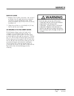
WARNING
Thin ice may result in the vicinity of the
discharge line.
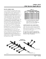
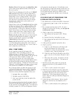
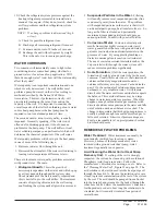
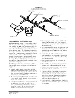
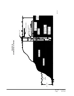
For complete information on water well systems and
lake and pond applications, refer to Manual 2100-078
available from your distributor.
L. Where the local conditions prevent the use of a
gravity drainage system to a lake or pond, you can
instead run standard plastic piping out into the pond
below the frost and low water level.
In the heating mode, heat is absorbed from the source
water loop. A boiler can be utilized to maintain the loop
at the desired temperature. In milder climates a
“flooded tower” concept is often used. This concept
involves adding makeup water to the cooling tower
sump to maintain the desired loop temperature.
TABLE 9
WATER FLOW AND PRESSURE DROP
M
P
G
2
4
2
W
Q
2
0
3
W
Q
,
1
2
4
W
Q
,
1
6
3
W
Q
1
8
4
W
Q
1
0
6
W
Q
G
I
S
P
.
d
H
.
t
F
G
I
S
P
.
d
H
.
t
F
G
I
S
P
.
d
H
.
t
F
G
I
S
P
.
d
H
.
t
F
3
0
0
.
1
1
3
.
2
-
-
-
-
-
-
-
-
-
-
-
-
-
-
-
-
-
-
4
2
4
.
1
8
2
.
3
0
0
.
1
1
3
.
2
-
-
-
-
-
-
-
-
-
-
-
-
5
3
8
.
1
2
2
.
4
3
4
.
1
0
3
.
3
0
8
.
1
5
1
.
4
-
-
-
-
-
-
6
4
2
.
2
7
1
.
5
6
8
.
1
9
2
.
4
8
2
.
3
7
5
.
7
-
-
-
-
-
-
7
6
6
.
2
4
1
.
6
0
3
.
2
1
3
.
5
7
7
.
4
1
0
.
1
1
-
-
-
-
-
-
8
-
-
-
-
-
-
3
7
.
2
0
3
.
6
6
2
.
6
6
4
.
4
1
0
3
.
3
3
6
.
7
9
-
-
-
-
-
-
-
-
-
-
-
-
5
7
.
7
0
9
.
7
1
0
3
.
4
4
9
.
9
0
1
-
-
-
-
-
-
-
-
-
-
-
-
4
2
.
9
4
3
.
1
2
0
0
.
5
5
5
.
1
1
1
1
-
-
-
-
-
-
-
-
-
-
-
-
-
-
-
-
-
-
0
0
.
6
6
8
.
3
1
2
1
-
-
-
-
-
-
-
-
-
-
-
-
-
-
-
-
-
-
0
0
.
7
7
1
.
6
1
3
1
-
-
-
-
-
-
-
-
-
-
-
-
-
-
-
-
-
-
0
2
.
8
5
9
.
8
1
Содержание QW242
Страница 6: ...Manual 2100 419E Page 6 of 48 FIGURE 1 UNIT DIMENSIONS ...
Страница 9: ...Manual 2100 419E Page 9 of 48 FIGURE 4 INSTALLATION OF UNIT THROUGH WALL WITH WALL SLEEVE MIS 1564 ...
Страница 21: ...Manual 2100 419E Page 21 of 48 FIGURE 15 REMOTE THERMOSTAT WIRING DIAGRAM X OPTION ...
Страница 22: ...Manual 2100 419E Page 22 of 48 FIGURE 16 REMOTE THERMOSTAT WIRING DIAGRAM A THERMOSTAT OPTION 4102 021A ...
Страница 23: ...Manual 2100 419E Page 23 of 48 4102 022C FIGURE 17 REMOTE THERMOSTAT WIRING DIAGRAM D THERMOSTAT OPTION ...
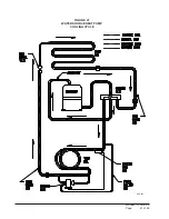
Страница 41: ...Manual 2100 419E Page 41 of 48 FIGURE 27 WATER SOURCE HEAT PUMP COOLING CYCLE MIS 329 ...
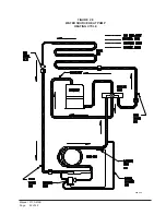
Страница 42: ...Manual 2100 419E Page 42 of 48 FIGURE 28 WATER SOURCE HEAT PUMP HEATING CYCLE MIS 328 ...


