Manual 2100-419E
Page
32 of 48
CIRCULATION SYSTEM DESIGN
Equipment room piping design is based on years of
experience with earth coupled heat pump systems. The
design eliminates most causes of system failure.
Surprisingly, the heat pump itself is rarely the cause.
Most problems occur because designers and installers
forget that a closed loop earth coupled heat pump
system is
not
like a household plumbing system.
Most household water systems have more than enough
water pressure either from the well pump of the
municipal water system to overcome the pressure of
head loss in 1/2 inch or 3/4 inch household plumbing.
A closed loop earth coupled heat pump system,
however, is separated from the pressure of the
household supply and relies on a small, low wattage
pump to circulate the water and antifreeze solution
through the earth coupling, heat pump and equipment
room components.
The small circulator keeps the operating costs of the
system to a minimum. However, the performance of the
circulator
must
be closely matched with the
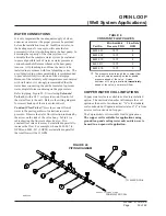
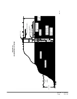
FIGURE 20
CIRCULATION SYSTEM
pressure of head loss of the entire system in order to
provide the required flow through the heat pump.
Insufficient flow through the heat exchanger is one of
the most common causes of system failure. Proper
system piping design and circulator selection will
eliminate this problem
Bard supplies a work sheet to simplify head loss
calculations and circulator selection. Refer to
“Circulating Pump Work sheet” section in manual
2100-099.
COPPER WATER COIL APPLICATION
Copper water coils are available as a factory installed
option. The unit model number will indicate the coil
option as the next to last character; “X” is for standard
coil constructed of Cupronickel material and “4” is from
a water coil constructed of copper.
The Cupronickel coil is suitable for all applications.
The copper coil is suitable for applications using
ground loop and cooling tower only and is never to
be used in an open well application.
CLOSED LOOP
(Earth Coupled Ground Loop Applications)
PIPE FROM GROUND LOOP
PIPE TO GROUND LOOP
PUMP MODULE
(See Spec Sheet for Model No.)
UNIONS
1” FLEXIBLE HOSE
Содержание QW242
Страница 6: ...Manual 2100 419E Page 6 of 48 FIGURE 1 UNIT DIMENSIONS ...
Страница 9: ...Manual 2100 419E Page 9 of 48 FIGURE 4 INSTALLATION OF UNIT THROUGH WALL WITH WALL SLEEVE MIS 1564 ...
Страница 21: ...Manual 2100 419E Page 21 of 48 FIGURE 15 REMOTE THERMOSTAT WIRING DIAGRAM X OPTION ...
Страница 22: ...Manual 2100 419E Page 22 of 48 FIGURE 16 REMOTE THERMOSTAT WIRING DIAGRAM A THERMOSTAT OPTION 4102 021A ...
Страница 23: ...Manual 2100 419E Page 23 of 48 4102 022C FIGURE 17 REMOTE THERMOSTAT WIRING DIAGRAM D THERMOSTAT OPTION ...
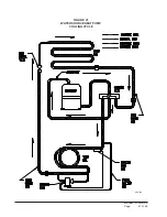
Страница 41: ...Manual 2100 419E Page 41 of 48 FIGURE 27 WATER SOURCE HEAT PUMP COOLING CYCLE MIS 329 ...
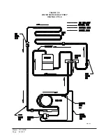
Страница 42: ...Manual 2100 419E Page 42 of 48 FIGURE 28 WATER SOURCE HEAT PUMP HEATING CYCLE MIS 328 ...


