Manual 2100-419E
Page
31 of 48
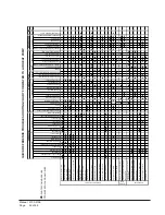
TABLE 7
OPTIONAL ACCESSORIES
O
p
ti
ona
l A
c
c
e
s
s
o
ri
e
s
–
M
u
s
t B
e
U
s
e
d
For
E
a
c
h
I
n
s
ta
ll
a
ti
on
W
/V
e
nti
la
ti
on
O
p
ti
ons
V
e
n
tila
tio
n
W
a
ll
S
le
e
v
e
s
:
Q
W
V
S
42
V
ent
ila
ti
on
w
all
s
leev
e f
o
r w
all
s up
t
o
14 i
nc
hes
t
hi
c
k
V
e
n
ti
la
ti
on O
ut
doo
r Lou
ve
r G
ri
ll
e
s
:
Q
L
G
-11
C
lea
r A
nodi
ze
d A
lum
inum
f
o
r
ve
nt
op
ti
o
n
Q
LG
-21
M
edium
B
ron
ze
A
n
odi
z
ed A
lu
m
inum
f
or
vent
opt
ion
Q
LG
-31
D
ar
k
B
ronz
e A
no
diz
ed
A
lum
inu
m
f
or
v
ent
opt
ion
O
pti
ona
l A
c
c
e
s
s
or
ie
s
–
For
G
round
Lo
op
Ins
ta
ll
a
ti
ons
W
G
P
M
-1C
S
in
gle
pum
p m
odu
le f
or
i
ndiv
idu
al
loop
s
y
s
tem
. 2
2 f
ee
t of
head
@
16 G
P
M.
I
ns
ta
lls
ins
ide
Q
W
u
nit
. 23
0V
60 H
z
–
1-
P
h
.
U
s
ed
w
it
h
all
mo
dels
,
in
cl
udi
ng 460
V
.
C
onne
ct
ions
ar
e
1 in
ch
F
P
T
.
F
u
lly i
n
su
lat
e
d c
abin
e
t.
W
G
P
M
-2C
D
ual
pum
p m
odul
e
for
indi
vid
ual
lo
op s
y
s
tem
.
44 f
eet
o
f hea
d @
16 G
P
M.
I
n
st
alls
ins
ide Q
W
uni
t.
230V
60 H
z
–
1-
P
h.
U
s
ed w
it
h al
l
model
s
,
in
cl
udi
ng 460
V
.
C
onne
ct
ions
ar
e
1 in
ch
F
P
T
.
F
u
lly i
n
su
lat
e
d c
abin
e
t.
W
G
R
K
-1
460
V
ol
t r
elay
k
it
.
R
e
quir
e
d w
hen
ins
ta
lli
ng
a pum
p m
odul
e i
n a
460 V
olt
.
W
G
H
K
-1
H
os
e k
it
f
or
p
ump
modul
e i
ns
tall
at
ions
.
C
o
nnec
ti
o
ns
ar
e 1
inc
h M
P
T
. I
nc
ludes
a
ll
par
ts
f
or
con
nec
ti
on
t
o
pump
mod
ule
an
d P
T
ad
apt
er
f
it
ti
n
g
s.
O
p
ti
o
n
a
l Acce
sso
ri
es –
Ad
d
it
io
n
a
l It
em
s A
s
D
e
te
rm
in
e
d
B
y
J
o
b
S
p
ec
if
ica
tio
n
s
N
O
T
E
:
T
h
e
fol
low
ing
ac
c
es
s
ory
i
tem
s
m
u
s
t b
e s
el
ec
ted s
o
that
t
he
fi
ni
s
h
(c
ol
or)
i
s
m
at
c
hed
to t
h
e
Q
W
m
o
del
t
hat
t
he
y
w
ill b
e
u
s
e
d
w
it
h
.
S
id
e
Tr
im
E
x
te
ns
io
n Ki
ts
:
R
equi
red
w
he
n w
all
t
hi
c
kn
ess
is
les
s
t
han 1
4 in
che
s
and w
or
k
s
f
or
w
al
ls
do
w
n
to 8
inc
he
s
t
hic
k.
U
s
ed i
n pl
ac
e of
s
tanda
rd t
rim
k
it
s
u
p
p
lie
d
w
it
h
un
it
t
o c
ov
er
t
h
e s
pac
e bet
w
e
en
unit
and
w
a
ll.
U
n
it
C
o
mp
atib
ili
ty
Q
S
T
X
42A
-V
P
la
tinu
m
v
inyl
Q
S
T
X
42-
A
4
G
ray
pain
t
A
ll Model
s
F
re
e
-B
lo
w
Pl
en
um
B
o
x
es:
U
n
it
C
o
mp
atib
ili
ty
Q
P
B
42-
V
P
la
tinu
m
v
inyl
Q
P
B
42-
4
G
ray
pain
t
F
ront
s
up
ply,
4-
w
ay
def
lec
ti
on gr
ill
e
A
ll
Model
s
Q
P
B
S
4
2-
V
P
la
tinu
m
v
inyl
Q
P
B
S
4
2-
4
G
ray
pain
t
S
am
e as
Q
P
B
42
, pl
us
2-
w
ay
def
ect
ion
gr
ill on
eac
h s
id
e
A
ll
Model
s
T
op
F
il
l
S
y
s
tem
s
f
o
r Fi
ni
shi
ng Pl
e
num
Box
e
s
t
o Ce
il
ings:
U
n
it
C
o
mp
atib
ili
ty
Q
PBX
4
2
-9
-V
Pla
tin
u
m
v
in
y
l
Q
PBX
4
2
-9
-4
G
ra
y
p
a
in
t U
s
e
w
ith
Q
PB4
2
o
r
Q
PBS4
2
(
a
d
ju
s
ts
to
c
e
ilin
g
s
u
p
t
o
9
’ 6
”)
A
ll
M
odel
s
Q
PBX
4
2
-1
0
-V
Pla
tin
u
m
v
in
y
l
Q
PBX
4
2
-1
0
-4
G
ra
y
p
a
in
t
U
s
e
w
ith
Q
PB4
2
o
r
Q
PBS4
2
(
a
d
ju
s
ts
to
c
e
ilin
g
s
u
p
t
o
1
0
’ 2
”)
A
ll
M
odel
s
Ca
bi
n
e
t E
x
te
ns
ions
for
D
uct
e
d
App
li
c
a
ti
o
ns:
U
n
it
C
o
mp
atib
ili
ty
Q
C
X
1
0A
-V
P
la
tinu
m
v
inyl
Q
C
X
1
0A
-4
G
ray
pain
t
2
0”
hei
ght
(
ad
jus
ts
f
or
c
ei
lings
u
p
t
o
9’
4”
; a
dd Q
P
B
X
4
2-
9
for
9
’ 4”
t
o
1
0’ f
ini
s
hed c
ei
lin
g hei
ght
s
)
A
ll Model
s
Ho
t W
a
te
r Co
il
s
wi
th
Pl
e
num
Box
e
s
:
U
n
it
C
o
mp
atib
ili
ty
Q
P
B
H
W
4
2-
F
-V
P
la
tinu
m
v
inyl
Q
P
B
H
W
4
2-
F
-4
G
ray pain
t
F
ree-
bl
ow
ple
num
bo
x
A
ll Model
s
Q
P
B
H
W
4
2-
D
-V
P
la
tinu
m
v
inyl
Q
P
B
H
W
4
2-
D
-4
G
ray pain
t
D
u
c
ted
pl
enum bo
x
A
ll Model
s
N
O
TE:
Th
e
s
a
me
t
o
p
f
ill s
y
s
te
m a
n
d
c
a
b
in
e
t
e
xt
e
n
s
io
n
s
c
a
n
b
e
u
s
e
d
w
it
h
h
o
t w
a
te
r c
o
il p
le
n
u
m b
o
x
e
s
a
s
w
it
h
s
tandar
d pl
enum
b
ox
es
.
Содержание QW242
Страница 6: ...Manual 2100 419E Page 6 of 48 FIGURE 1 UNIT DIMENSIONS ...
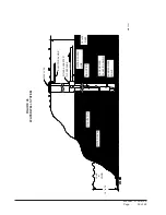
Страница 9: ...Manual 2100 419E Page 9 of 48 FIGURE 4 INSTALLATION OF UNIT THROUGH WALL WITH WALL SLEEVE MIS 1564 ...
Страница 21: ...Manual 2100 419E Page 21 of 48 FIGURE 15 REMOTE THERMOSTAT WIRING DIAGRAM X OPTION ...
Страница 22: ...Manual 2100 419E Page 22 of 48 FIGURE 16 REMOTE THERMOSTAT WIRING DIAGRAM A THERMOSTAT OPTION 4102 021A ...
Страница 23: ...Manual 2100 419E Page 23 of 48 4102 022C FIGURE 17 REMOTE THERMOSTAT WIRING DIAGRAM D THERMOSTAT OPTION ...
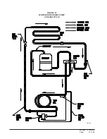
Страница 41: ...Manual 2100 419E Page 41 of 48 FIGURE 27 WATER SOURCE HEAT PUMP COOLING CYCLE MIS 329 ...
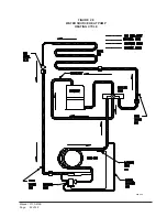
Страница 42: ...Manual 2100 419E Page 42 of 48 FIGURE 28 WATER SOURCE HEAT PUMP HEATING CYCLE MIS 328 ...


