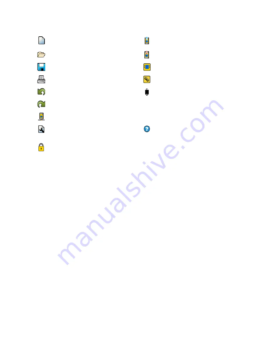
(1) Navigation Toolbar
Starts a New project
Reads the data, such as Fault Log, Configuration, Network
Settings, and Device Information from the Safety
Controller
Opens an existing project, opens a Recent project, or
opens Sample Projects
Writes the data, such as Configuration Settings to the
Safety Controller
Saves (or Save As) the project to the user-defined location
Makes the Live Mode view available
Prints a customizable Configuration Summary
Makes the Simulation Mode view available
Reverts up to ten previous actions
Indicates SC-XM2 or SC-XM3 drive connection
Re-applies up to ten previously reverted actions
Opens the Help options
•
Help—Opens Help topics
•
About—Displays Software version number and
user responsibilities warning
•
Release Notes—Displays the release notes for
each version of the software
•
Icons—Switches between US- and European-
style icons
•
Support Information—Describes how to request
help from the Banner Advanced Technical
Support Group
•
Language—Selects the Software language
options
Displays Network Settings and writes the Network
Settings to the Safety Controller
Displays Project Settings
Opens Password Manager
(2) Tabs for Worksheets and Diagrams
Equipment—Displays an editable view of all connected equipment
Functional View—Provides editable iconic representation of the control logic
Wiring Diagram—Displays the I/O device wiring detail for the use by the installer
Ladder Logic—Displays a symbolic representation of the Safety Controller’s safeguarding logic for the use by the
machine designer or controls engineer
Industrial Ethernet(when enabled) —Displays editable network configuration options
Configuration Summary—Displays a detailed configuration summary
Live Mode (when enabled)—Displays the live mode data, including current faults
Simulation Mode (when enabled)—Displays the simulation mode data
(3) Selected View
Displays the view corresponding to the selected tab (Equipment view shown)
(4) Module Summary
Displays the Base Controller and any connected modules or displays the SC10-2
(5) Check List
Provides action items to configure the system and correct any errors to successfully complete the configuration
(6) Properties
Displays the properties of the selected device, function block, or connection (properties cannot be edited in this
view; click Edit below to make changes)
Delete—Deletes the selected item
Edit—Displays the configuration options for the selected device or function block
on page 144 for issues related to the Software functionality.
XS/SC26-2 and SC10-2 Safety Controllers
74
www.bannerengineering.com - Tel: + 1 888 373 6767


