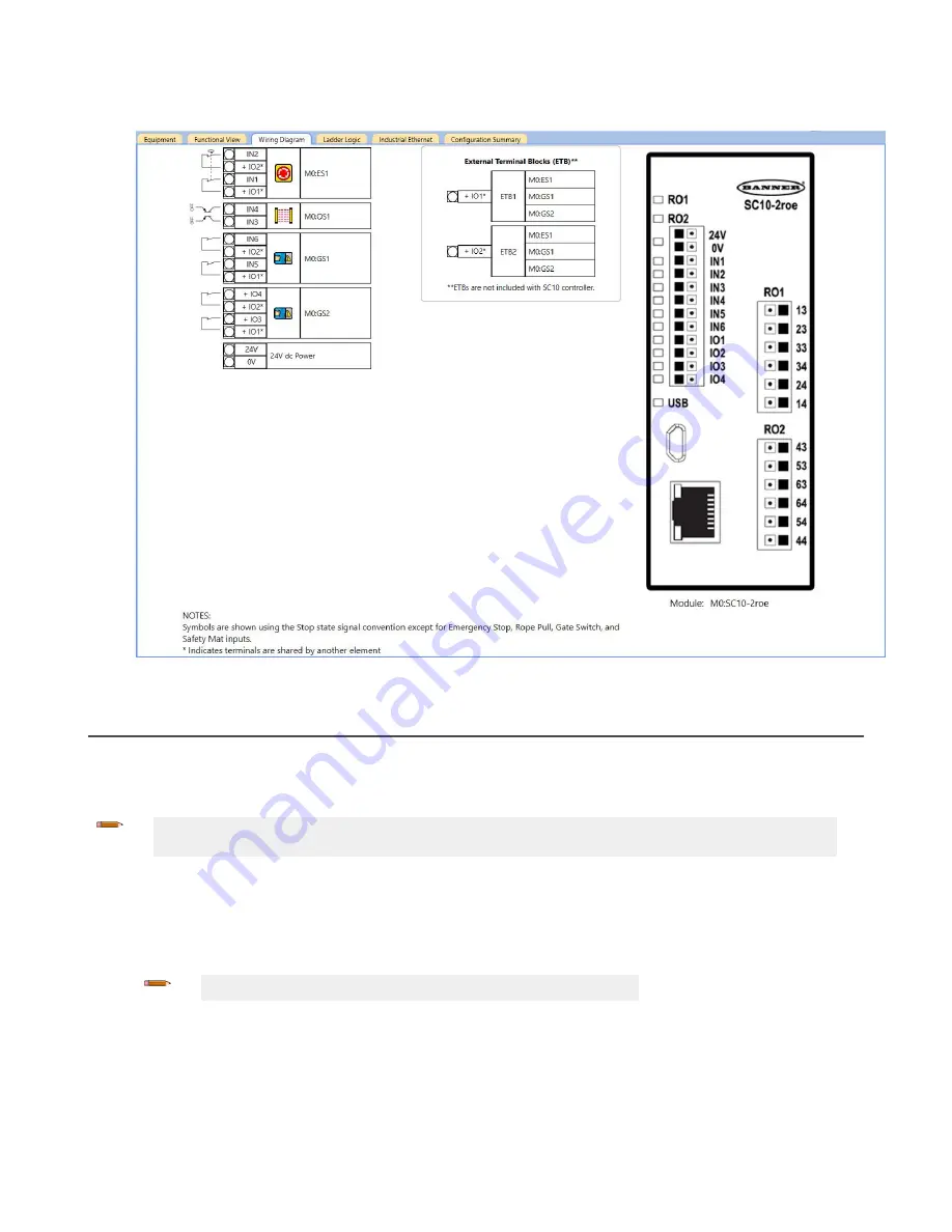
18. Go to the Wiring Diagram tab and notice the second Gate Switch has been added and no additional ETB has been
added.
Figure 115. Wiring Diagram tab with an E-stop button, optical sensor, gate switches, and ETBs
12.9
SC10-2
Using the SC-XM3
Use an SC-XM3 to:
• Quickly configure multiple SC10-2 Safety Controllers with the same configuration
• Replace one SC10-2 Safety Controller with another using the SC-XM3 from the old Safety Controller
Note: The Banner Engineering programming tool (SC-XMP2) and Software are required to write a
confirmed configuration to an SC-XM3. This limits access to authorized personnel.
1. Create the desired configuration using the Software.
2. Confirm the configuration by loading it onto an SC10-2.
3. Review and approve the results.
After review and approval, the configuration can be saved and used by the Safety Controller.
4. Write the confirmed configuration to the SC-XM3 using the programming tool.
Note: Only confirmed configurations can be stored on the SC-XM3.
5. Use a label to indicate the configuration that is stored on the SC-XM3.
6. Install and/or connect power to the desired SC10-2 (new Safety Controller or replacement Safety Controller).
• If the SC10-2 is a factory default Safety Controller, the power/fault LED is on green and the USB LED flashes
green to indicate that the Safety Controller is waiting for a configuration.
• If the SC10-2 is a configured Safety Controller, the power/fault LED is on green and the USB LED is on red.
XS/SC26-2 and SC10-2 Safety Controllers
www.bannerengineering.com - Tel: + 1 888 373 6767
141


