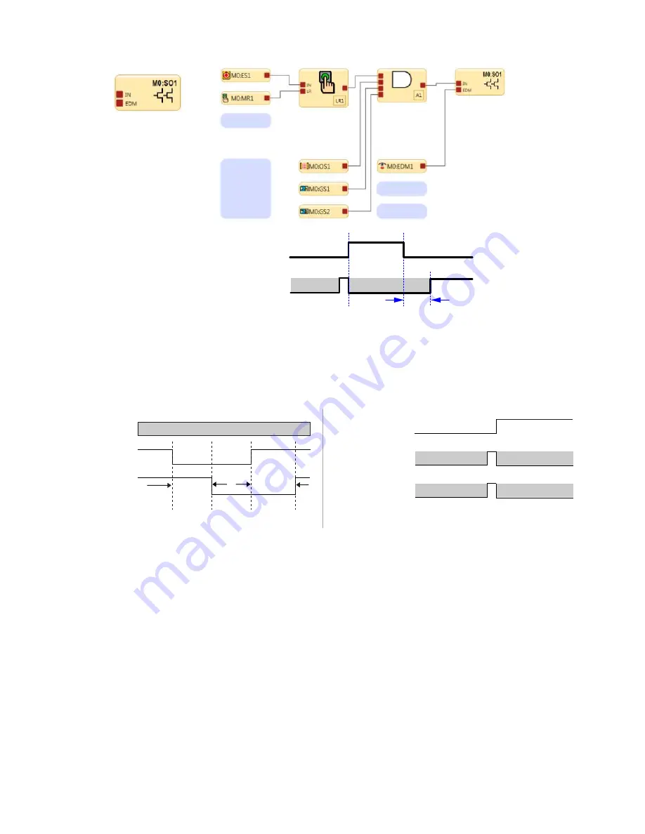
External Device Monitoring EDM is a way to check the operation of dual channel final switching
devices or machine primary control elements. The force guided N.C. monitoring contacts of the
FSD or MPCE are used as an input to detect a “stuck on” fault condition and will prevent the safety
controller outputs from turning On.
External Device
Monitoring
250 ms
250 ms
Don’t Care
Don’t Care
Closed
Open
SO1
EDM
Figure 36. Timing logic: One-channel EDM status, with respect to Safety Output
For two-channel EDM, as shown below, both channels must be closed before the Safety Output(s) turn On.
Safety Output
250 ms
Max.
250 ms
Max.
250 ms
Max.
250 ms
Max.
250 ms
Max.
250 ms
Max.
Don’t Care
Closed
Open
Closed
Open
EDM 1
EDM 2
Figure 37. Timing logic: Two-channel EDM, timing between channels
Safety Output
Must Match EDM 2
Must Match EDM 2
ON
OFF
Closed
Open
EDM 1
Must Match EDM 1
Must Match EDM 1
Closed
Open
EDM 2
Figure 38. Timing logic: Two-channel EDM status, with respect to Safety
Output
FSD Interfacing Connections
Final switching devices (FSDs) interrupt the power in the circuit to the Machine Primary Control Element (MPCE) when the
Safety Outputs go to the Off-state. FSDs can take many forms, though the most common are forced-guided (mechanically
linked) relays or Interfacing Modules. The mechanical linkage between the contacts allows the device to be monitored by
the external device monitoring circuit for certain failures.
Depending on the application, the use of FSDs can facilitate controlling voltage and current that differs from the Safety
Outputs of the Safety Controller. FSDs may also be used to control an additional number of hazards by creating multiple
safety stop circuits.
Safety (Protective) Stop Circuits
A safety stop allows for an orderly cessation of motion or hazardous situation for safeguarding purposes, which results in a
stop of motion and removal of power from the MPCEs (assuming this does not create additional hazards). A safety stop
circuit typically comprises a minimum of two normally open contacts from forced-guided (mechanically linked) relays, which
are monitored (via a mechanically linked NC contact) to detect certain failures so that the loss of the safety function does
not occur. Such a circuit can be described as a “safe switching point.”
XS/SC26-2 and SC10-2 Safety Controllers
www.bannerengineering.com - Tel: + 1 888 373 6767
55


