5 - 15
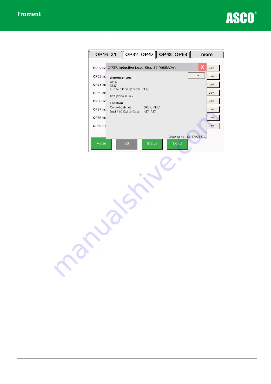
Figure 5-8
Tapping an input or output key opens a pop-up window with more detailed
information.
The I/O screens show the state of each input or output. These are shown green when they
are active. Low = 0Vdc and high = +24Vdc.
The detailed view shows the input or output’s dependencies by listing the component
identifications for the selected circuit.
In the example above:
•
Load Bank Module output OP37 drives relay K137 which in turn drives the load step
contactor K37.
•
K37 is 465kVAr inductive load step rated at 690V/50Hz.
•
The load step fuse is F37 rated at 500A.
The location of each component is also detailed along with the Froment drawing number
which shows the circuit.
Maintenance & Troubleshooting
Содержание Froment 8800 Series
Страница 1: ...8800 SERIES High Voltage Load Banks User Manual Power Technologies ...
Страница 2: ......
Страница 10: ......
Страница 42: ...Load Bank Installation and Setup 2 14 ...
Страница 106: ...A 4 Appendices Figure A 5 8800 Transformer view ...
Страница 110: ...A 8 Appendices Transformer Maintenance Schedule ...


