19
E
ngl
is
h
M/
Q1
M/
Q3
T/Y
10
50-65 mm
T/Y2
T/Y2
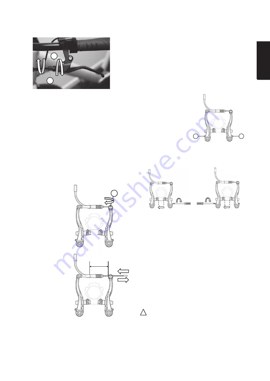
For
minor
adjustments, you can turn the brake lever
adjustment screw (M/Q1) for cable tension.
The brake arm spring tension
• The brake arms are spring-loaded, which means that
they are pushed outwards away from the rim when
the brake lever is not pulled.
• The tension of the spring-loading must be the same
for both brake arms in order to ensure that the braking
force and the distance between the brake pads and
the rims is equal on both sides.
• The braking system works most effectively when
the force of the brake arms’ spring-loading is as low as
possible while also being fully adequate for the brake
arms to spring outwards, without obstruction, when
you release the brake lever.
1. Turn the locking ring (M/Q3) against
the adjustment screw.
-
Turn the adjustment screw (together with
the locking ring) outwards/anti-clockwise to
increase the cable tension. The distance between
the brake pads and wheel rims becomes smaller.
The brake lever moves away from the handlebars.
-
Turn the adjustment screw inwards/clockwise to
decrease the cable tension. The distance between
the brake pads and wheel rims becomes greater.
The brake lever moves closer to the handlebars.
2. Finally, tighten the locking ring against the brake lever
in order to fix the position of the adjustment screw.
If
greater
adjustments are required (which cannot be
achieved using the adjustment screw), you must adjust
the position of the brake cable (T/Y9) on the brake arm.
1. Hold the end of
the cable while you
loosen the socket
head screw (T/Y10)
(5 mm).
2. Pull the cable out
from the brake
arm to tighten
the cable, or push
in the opposite
direction to
loosen the cable.
The distance
between the cable’s
attachment to
the brake arm and
the link on the other
brake arm must be
50–65 mm.
3. Tighten the screw.
4. Finely-tune this adjustment as necessary, in
accordance with step 1.
• The tension of
the spring is adjusted
using a screw next to
the brake arm pivot
point (T/Y2).
1. Test the brakes repeatedly while observing both
the movement of the brake arms and the distance
between the brake pads and the rims. Test whether it
requires much or little force to pull the brake lever.
2. If the brake arms
move unevenly, or if
the brake pads are
at unequal distances
from the rim, turn
the adjusting screw
(in an anti-clockwise
direction) on the brake
arm that either moves
the most or whose
brake pad is furthest
from the rim.
3. If adjusting the screw in
accordance with step 2
does not result in any
change, you should turn
the adjusting screw (in
a clockwise direction) on
the brake arm that moves
the least or whose brake
pad is closest to the rim.
Test the brakes repeatedly
while turning the screw
in order to see the direct
results of the adjustment.
4. If the brake arms move evenly but you think that
the brake lever is stiff and hard to pull, try turning
the adjustment screws on both brake arms in an anti-
clockwise direction.
Note:
• Adjust the screws evenly on both sides until
the resistance of the brake lever decreases.
• Make sure that you do not loosen the screws so much
that they fall off. If you reduce the tension too much,
the brake arms will not spring outwards. If this happens,
turn the adjustment screws in a clockwise direction.
Содержание 31-9779
Страница 2: ......


