160
include the feed motor) The purpose of this procedure is to avoid the marker pulse and the reference position
from occurring together
Machine Reference Process
Overview
All the position movements of the
CR
machine and the
T-UNIT
presses are digital values. These values are
based on a known starting position of “0”. This position is displayed in encoder counts (feedback units or FBU’s).
This position is established when the machine is built. It must also be re-established any time the mechanical
integrity of an axis is broken. This would be in the case of a belt or motor replacement. This is known as
“The
Master Reference”
. This position is based on the relationship of the fixtured positions of all axes and the one-
revolution marker pulse in the motor encoders. (Index Data)
Each time the machine is restarted from an un-powered state a “Machine Reference” will occur. If so equipped
the T-Unit presses will reference also. This will also occur if the CPU cards are manually reset.
Master Reference (
CR
)
The process of establishing a “
Master Reference
” is done with a master reference fixture. This fixture holds each
axis in the “0” position. The use of this fixture is described below. Following the process the machine will first
digitally mark its position in the fixture. Continuing through the described process the machine will make a series
of moves to find the marker pulse relative to the fixtured position.
Now the number of FBU’s between the marker pulse and the “0” position has been established.
Machine Reference
Each Time the machine CPU boots it will require a Machine Reference. This happens when the machine is
powered up or the CPU is manually reset.
I should be noted that whenever the machine CPU is manually reset it is necessary to restart the UNITY program.
During the Machine Reference, each axis will move to find the marker pulse. These are not calculated moves.
They are just continues moves until the marker pulse is found. From the marker pulse the axis will return to “0”
using the information stored the Master Reference Procedure.
Master Reference Procedure.
Setting Mechanical Index Position
Each axis has position at which the marker (Index data) pulse occurs. If the connection between the motor and
the end effect is broken, these positions need to be re-established
Infeed pivot arm, - 20° CCW form the center of the cutter head.
Outfeed pivot arm, - 20° CCW form the center of the cutter head.
Infeed strip stroke/Outfeed strip stroke – fully extended then back about 10 mm (.375”)
Cutter head. - One half turn from fully closed.
Содержание CR.11
Страница 129: ...129 8M Sec guard Notice this transition ...
Страница 145: ...145 ...
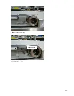
Страница 174: ...174 Spacer block not installed Spacer block installed Spacer block ...
Страница 178: ...178 Installing the monitor Use the 4 screws provided to mount the monitor Plug in the cords UBS cord from computer ...
Страница 182: ...182 The wiring diagram in shows the main power connection coming into the machine ...

