152
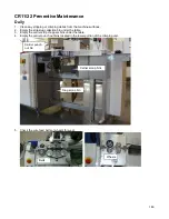
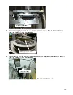
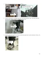
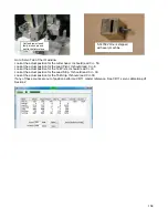
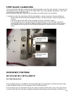
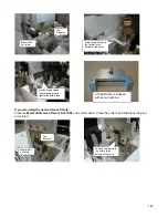
3. Remove the back cover of the cutter head. Clean and then grease the ball screw with Ball and Slide grease
916-450. Reassemble when finished.
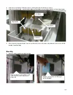
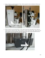
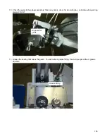
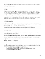
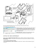
4. Remove the grey cover from each pivot arm, you may need to remove the wire collector cover. Clean any
debris from the rack and pinion gear. Move the arm from one side of the rack to the other, make sure it is not
binding at either end or has a lot of play in either end. Apply a small amount of quad ring lubricant 919-021
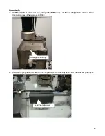
See Quarterly maintenance step 2 for pictures of the leading arm.
Remove the cutting head cover.
Ball screw
Tail pivot arm cover
Содержание CR.11
Страница 129: ...129 8M Sec guard Notice this transition ...
Страница 145: ...145 ...
Страница 174: ...174 Spacer block not installed Spacer block installed Spacer block ...
Страница 178: ...178 Installing the monitor Use the 4 screws provided to mount the monitor Plug in the cords UBS cord from computer ...
Страница 182: ...182 The wiring diagram in shows the main power connection coming into the machine ...

