


82
measurements will be the bed of the flume. Carefully adjust the level gauges to coincide
with the bed of the flume and record the datum readings.
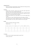
Procedure
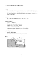
Gradually open the flow control valve and allow the channel upstream of the siphon to
fill with water. Reduce the flowrate as the water level reaches the crest of the siphon tube
then gradually increase the flow again.
Open the inlet valve and gradually increase the flow to the siphon taking great care not to
overload the siphon. It takes a little time for the siphon to prime and increasing the flow
too quickly will cause the flow to flood over the top of the siphon. Gradually allow the
downstream channel to fill with water so that the siphon outlet is submerged. Add stop
logs if necessary until the hood at the outlet of the siphon is just submerged.
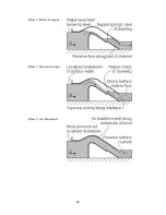
Adjust the flow control valve to a very low flow and observe the free weiring flow.
Increase the flowrate so that the upstream water level rises and seals the inlet.
Observe the priming action and deflected nappe flow as air is drawn in through the inlet
and evacuated through the outlet. Increase the flow and observe the gradual change to the
depressed nappe flow. At certain flows the siphon may alternate between deflected nappe
and depressed nappe flow.
Increase the flow further and observe the air partialised and “blackwater” flow conditions.
Because of the increased flow the downstream water level will have risen above the
original priming level. To ensure a vigorous air flow, gradually lower the tailwater level
by removing stop logs as the flow increases but make sure the outlet is always drowned.
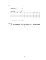
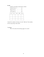
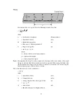
While operating in the blackwater condition measure the upstream level y
0
and the
downstream level y
1
using the level gauges then measure the volume flowrate Q using the
direct reading flowmeter or volumetric tank with a stopwatch.
Observe the effect of different tailwater levels on the initial priming action and on air
regulation for the different flow phases.
Содержание C4-MKII
Страница 1: ...An ISO 9001 Company INSTRUCTION MANUAL C4 MKII ISSUE 7 SEPTEMBER 2006 MULTI PURPOSE TEACHING FLUME...
Страница 2: ......
Страница 8: ......
Страница 10: ...8 1 1 Diagram 1 Inlet End of Flume 1 2 3 5 6 8 7 4...
Страница 11: ...9 1 2 Diagram 2 Discharge End of Flume 10 3 1 8 2 7 9 11...
Страница 82: ...80 Phase 2 Deflected nappe Phase 3 Depressed nappe Phase 4 Air Partialised...


