

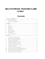


MULTI-PURPOSE TEACHING FLUME
C4-MKII
Contents
1
Introduction to the Equipment ......................................................................................................................... 7
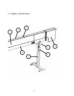
1.1
Diagram 1: Inlet End of Flume .................................................................................................................. 8
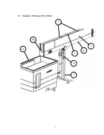
1.2
Diagram 2: Discharge End of Flume......................................................................................................... 9
2
Description........................................................................................................................................................ 10
2.1
Overview .................................................................................................................................................. 10
2.2
Working Section ....................................................................................................................................... 10
2.3
Inlet Tank ................................................................................................................................................. 10
2.4
Overshot Weir .......................................................................................................................................... 10
2.5
Optional Flowmeter ................................................................................................................................. 10
2.6
Hook and Point Gauges ........................................................................................................................... 11
2.7
Pedestals and Jack ................................................................................................................................... 11
2.8
The F1-10 Hydraulics Bench ................................................................................................................... 11
3
Operation.......................................................................................................................................................... 13
3.1
Positioning the F1-10 Hydraulics Bench ................................................................................................. 13
3.2
Connecting the F1-10 Hydraulics Bench ................................................................................................. 13
3.3
Filling the F1-10 Hydraulics Bench with water....................................................................................... 14
3.4
Assembling and Installing Models ........................................................................................................... 14
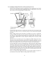
3.5
Assembling and Installing the Venturi Flume .......................................................................................... 15
3.6
Installing the Optional False Floor Sections ........................................................................................... 15
3.7
Installing the Optional Roughened Bed Sections ..................................................................................... 16
3.8
Sealing models into the flume................................................................................................................... 16
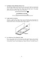
3.9
Use of Stop Logs to Vary Flume Flow Depth........................................................................................... 16
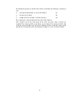
3.10
Installing the Optional Pitot Tube and Manometer Board (C4-61)......................................................... 17
3.11
Operating the Optional Pitot Tube and Manometer (C4-61)................................................................... 18
3.12
Installing the Optional Wave Generator (C4-67)..................................................................................... 20
3.13
Operating the Optional Wave Generator (C4-67) ................................................................................... 20
Содержание C4-MKII
Страница 1: ...An ISO 9001 Company INSTRUCTION MANUAL C4 MKII ISSUE 7 SEPTEMBER 2006 MULTI PURPOSE TEACHING FLUME...
Страница 2: ......
Страница 8: ......
Страница 10: ...8 1 1 Diagram 1 Inlet End of Flume 1 2 3 5 6 8 7 4...
Страница 11: ...9 1 2 Diagram 2 Discharge End of Flume 10 3 1 8 2 7 9 11...
Страница 82: ...80 Phase 2 Deflected nappe Phase 3 Depressed nappe Phase 4 Air Partialised...


