


28
by the walls and the bed. Although leakage may not be evident, check the seal between
the clear acrylic panels and the bed of the channel. Apply silicone sealant to the corner of
the joint if any doubt exists.
All PVC and rubber hoses/sleeves must be checked and replaced if perished.
Despite appearing leak-tight, all joints should be checked for integrity and re-seated if
necessary.
Leaks from threaded joints should be sealed by wrapping PTFE tape around the thread
before refitting.
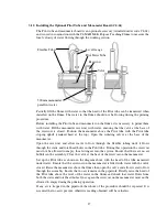
5.6.6
Lubrication
All moving parts should be lubricated using a general purpose grease. Special attention
should be paid to the pivot, the jacking arrangement and the trunnions attaching the flume
to the support pedestals.
Where usage is unusually heavy or local conditions are extreme increase the frequency of
lubrication to every 6 months.
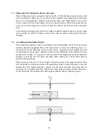
5.6.7
Check that channel section is straight and level
Refer to the Installation Guide at the end of this instruction manual for details on how to
check that the channel section is straight and level before refilling the system.
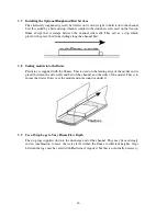
5.6.8
Refilling
Refill the F1-10 Hydraulics Bench as described in the Operation section or Installation
Guide of this manual.
5.6.9
Cleaning the Models
Models used in the channel should be checked for damage and repaired if necessary. All
models should be washed in warm water to which household detergent has been added.
Many of the models use clear acrylic or rigid PVC in the construction and should not be
cleaned using strong solvents such as acetone, trichloroethylene or tetrachloride which
will soften the material and cause crazing of the clear acrylic.
In order to restore visual clarity to scuffed, discoloured or surface crazed acrylic, an
abrasive metal polish may be used.
Содержание C4-MKII
Страница 1: ...An ISO 9001 Company INSTRUCTION MANUAL C4 MKII ISSUE 7 SEPTEMBER 2006 MULTI PURPOSE TEACHING FLUME...
Страница 2: ......
Страница 8: ......
Страница 10: ...8 1 1 Diagram 1 Inlet End of Flume 1 2 3 5 6 8 7 4...
Страница 11: ...9 1 2 Diagram 2 Discharge End of Flume 10 3 1 8 2 7 9 11...
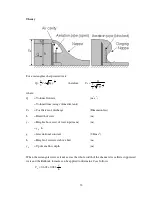
Страница 82: ...80 Phase 2 Deflected nappe Phase 3 Depressed nappe Phase 4 Air Partialised...


