


46
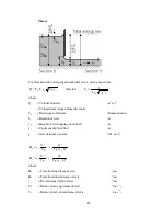
Equipment Set Up
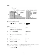
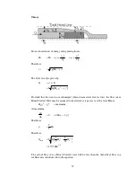
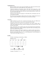
Ensure the flume is level, with no stop logs installed at the discharge end of the channel.
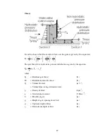
Measure and record the actual breadth b (m) of the undershot weir.
Clamp the undershot weir assembly securely to the sides of the channel at a position
approximately mid way along the flume with the sharp edge on the bottom of the weir
facing upstream. For accurate results the gaps between the weir and the channel should be
sealed on the upstream side using Plasticine.
Position two hook and point level gauges on the channel sides, one upstream of the weir
and one downstream of the weir, each with the point fitted.
The datum for all measurements will be the bed of the flume. Carefully adjust the level
gauges to coincide with the bed of the flume and record the datum readings.
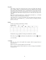
Procedure
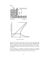
Adjust the knob on top of the weir to position the sharp edge of the weir 0.020m above
the bed of the flume.
Gradually open the flow control valve and admit water until y
o
= 0.200m measured using
the upstream level gauge. With y
o
at this height, measure Q using the direct reading
flowmeter or the volumetric tank with a stopwatch. Also measure y
1
using the
downstream level gauge. Raise the weir in increments of 0.010m maintaining y
o
at the
height of 0.200m by varying the flow of water. At each level of the weir record the values
of Q and y
1
.
Repeat the procedure with a constant flow Q allowing y
o
to vary. Record the values of y
0
and y
1
.
Содержание C4-MKII
Страница 1: ...An ISO 9001 Company INSTRUCTION MANUAL C4 MKII ISSUE 7 SEPTEMBER 2006 MULTI PURPOSE TEACHING FLUME...
Страница 2: ......
Страница 8: ......
Страница 10: ...8 1 1 Diagram 1 Inlet End of Flume 1 2 3 5 6 8 7 4...
Страница 11: ...9 1 2 Diagram 2 Discharge End of Flume 10 3 1 8 2 7 9 11...
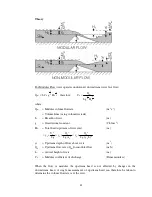
Страница 82: ...80 Phase 2 Deflected nappe Phase 3 Depressed nappe Phase 4 Air Partialised...


