


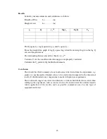

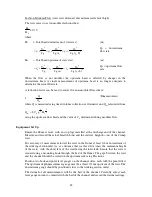


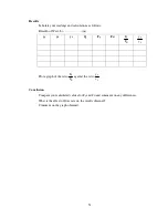

38
2
3
0
d
actual
H
b
C
704
.
1
Q
=
where C
d
is the coefficient of discharge.
i.e.
Q
actual
= C
d
x Q
theoretical
The Coefficient of Discharge may therefore be determined as
C
d
=
Rate
Flow
l
Theoretica
Rate
Flow
Actual
Equipment Set Up
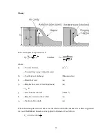
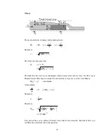
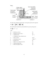
Ensure the flume is level, with no stop logs installed at the discharge end of the channel.
Measure and record the actual breadth b (m) of the broad crested weir.
Install the weir in the flume with the rounded corner upstream. Ensure that the weir is
secured using a mounting hook through the bed of the flume. For accurate results the gaps
between the weir and the channel should be sealed on the upstream side using Plasticine.
Position two hook and point level gauges on the channel sides, adjacent to the weir, each
with the point fitted.
The datum for all measurements will be the crest of the weir. Carefully adjust the level
gauges to coincide with the top of the weir and record the datum readings. Using one
level gauge carefully measure the height of the weir above the bed h
w
(m) taking care not
to damage the surface of the weir. Position this level gauge above the weir near to the
discharge end. Position the second level gauge some way upstream from the weir.
Procedure
Adjust the flow of water into the flume to obtain heads y
0
, increasing in about 0.010m
steps. For each step measure the flowrate Q
actual
, the upstream depth of flow above the
weir y
0
and the depth of flow over the weir y
1
(where the flow becomes parallel to the
weir). The flowrate Q
actual
can be determined using the direct reading flowmeter or the
volumetric tank with a stopwatch. For accurate results the level gauge must be far enough
upstream to be clear of the draw-down over the weir.
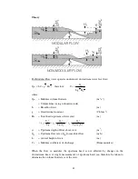
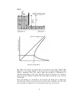
At each setting also observe and sketch the flow patterns over the weir.
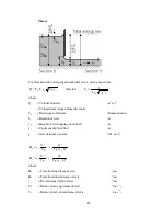
Gradually increase the total depth of the water downstream of the weir by adding stop
logs at the discharge end of the channel. For each step measure the flowrate Q
actual
, the
upstream depth of flow y
0
and the depth of flow over the weir y
1
. Observe and sketch the
flow patterns over the weir.
Содержание C4-MKII
Страница 1: ...An ISO 9001 Company INSTRUCTION MANUAL C4 MKII ISSUE 7 SEPTEMBER 2006 MULTI PURPOSE TEACHING FLUME...
Страница 2: ......
Страница 8: ......
Страница 10: ...8 1 1 Diagram 1 Inlet End of Flume 1 2 3 5 6 8 7 4...
Страница 11: ...9 1 2 Diagram 2 Discharge End of Flume 10 3 1 8 2 7 9 11...
Страница 82: ...80 Phase 2 Deflected nappe Phase 3 Depressed nappe Phase 4 Air Partialised...


