Armfield C4-MKII Скачать руководство пользователя страница 7


4


Specifications .................................................................................................................................................... 22


4.1


Overall Dimensions .................................................................................................................................. 22


4.2


Working Section Dimensions.................................................................................................................... 22


4.3


Flume Slope.............................................................................................................................................. 22


4.4


Flow Rate ................................................................................................................................................. 22


4.5


Electrical Supply ...................................................................................................................................... 23


4.6


Water Supply and Drain........................................................................................................................... 23


4.7


Hook and Point Gauges (2 supplied) ....................................................................................................... 23


4.8


Models Available for Use in the C4-MkII Flume ..................................................................................... 23


5


Routine Maintenance....................................................................................................................................... 25


5.1


General..................................................................................................................................................... 25


5.2


RCD test for F1-10 Hydraulics Bench ..................................................................................................... 25


5.3


Test condition of water in F1-10 Hydraulics Bench................................................................................. 25


5.4


Check C4-MkII for leaks .......................................................................................................................... 25


5.5


Check condition of channel bed ............................................................................................................... 26


5.6


Full annual service................................................................................................................................... 26


6


Laboratory Teaching Exercises ...................................................................................................................... 29


6.1


Index to Exercises..................................................................................................................................... 29


6.2


General Nomenclature ............................................................................................................................. 30


6.3


Nomenclature for Free Surface Flow....................................................................................................... 31


6.4


Exercise A: Sharp Crested Overshot Weir ............................................................................................... 32


6.5


Exercise B: Broad Crested Weir .............................................................................................................. 36


6.6


Exercise C: Crump Weir........................................................................................................................... 40


6.7


Exercise D: Discharge Beneath a Sluice Gate ......................................................................................... 44


6.8


Exercise E: Force on a Sluice Gate ......................................................................................................... 48


6.9


Exercise F: The Specific Energy Equation............................................................................................... 52


6.10


Exercise G: The Hydraulic Jump ............................................................................................................. 57


6.11


Exercise H: Flow Through a Venturi Flume ............................................................................................ 61


6.12


Exercise J: Flow Through a Culvert ........................................................................................................ 65


6.13


Exercise K: Flow Around Flow Splitters.................................................................................................. 68


6.14


Exercise L: Flow Over a Dam Spillway ................................................................................................... 71


6.15


Exercise M: Flow Through a Siphon Spillway......................................................................................... 74


6.16


Exercise N: Flow Through an Air Regulated Siphon ............................................................................... 78


6.17


Exercise P: Flow Under a Radial Gate.................................................................................................... 84


6.18


Exercise Q: Flow Over False Floor Sections........................................................................................... 87


6.19


Exercise R: Flow Over a Gravel Bed ....................................................................................................... 90


7


Installation Guide................................................................................................................................................i


Содержание C4-MKII

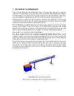
Страница 1: ...An ISO 9001 Company INSTRUCTION MANUAL C4 MKII ISSUE 7 SEPTEMBER 2006 MULTI PURPOSE TEACHING FLUME...

Страница 2: ......

Страница 3: ...gers may exist if the equipment is misused mishandled or badly maintained Electrical Safety The equipment described in this Instruction Manual operates using a service unit the F1 10 Hydraulics Bench...

Страница 4: ...he equipment Do not touch any moving components while the Wave Generator is in use or insert any item into any moving or rotating section of the equipment Ensure that the apparatus is switched off and...

Страница 5: ...d for cleanliness Under the COSHH regulations the following precautions must be observed Any water contained within the product must not be allowed to stagnate i e the water must be changed regularly...

Страница 6: ...13 3 2 Connecting the F1 10 Hydraulics Bench 13 3 3 Filling the F1 10 Hydraulics Bench with water 14 3 4 Assembling and Installing Models 14 3 5 Assembling and Installing the Venturi Flume 15 3 6 Ins...

Страница 7: ...ure 30 6 3 Nomenclature for Free Surface Flow 31 6 4 Exercise A Sharp Crested Overshot Weir 32 6 5 Exercise B Broad Crested Weir 36 6 6 Exercise C Crump Weir 40 6 7 Exercise D Discharge Beneath a Slui...

Страница 8: ......

Страница 9: ...e in operation A set of basic models is included with all versions of the flume A range of optional models is also available to extend the experimental capabilities This manual covers all versions of...

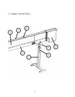
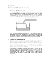
Страница 10: ...8 1 1 Diagram 1 Inlet End of Flume 1 2 3 5 6 8 7 4...

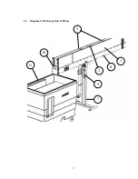
Страница 11: ...9 1 2 Diagram 2 Discharge End of Flume 10 3 1 8 2 7 9 11...

Страница 12: ...n along the length of the working section See section 2 6 2 3 Inlet Tank Water enters the parallel working section via the inlet tank 4 that is constructed from PVC The water pipe entering the inlet t...

Страница 13: ...et end of the working section is fitted with a hand operated jack This jacking arrangement permits the slope of the channel bed to be manually adjusted The jack is operated by a handwheel 5 and the me...

Страница 14: ...glass level gauge This reading in litres is used to find the actual flow rate by referring to the following table Flow Rate Reference Table Only used with C4 MKII up to 1 6 l s Scale Reading Litres F...

Страница 15: ...tioning 3 2 Connecting the F1 10 Hydraulics Bench Disconnect any accessory that is already connected to the quick release connector on the F1 10 connector located inside the top moulded channel on the...

Страница 16: ...odels with the exception of the Venturi flume the false floor sections and the artificially roughened bed as described in later sections are hooked in place via a retaining bar on the underside of the...

Страница 17: ...etcher screw This is placed between the two sections of the Venturi and adjusted to clamp them against the side walls of the channel NOTE The stretcher must be placed above the level of the water so a...

Страница 18: ...ing models into the flume Plasticine is supplied with the flumes This is used on the leading edge of the model and is placed between the side walls and bed of the channel and the sides of the model Th...

Страница 19: ...ntil it flows through the static and total head holes in the Pitot tube During this operation the reservoir must not be allowed to empty thus letting air into the system Ensure that there are no air b...

Страница 20: ...with excessively high velocities the paraffin will be pushed out of the manometer into the flexible tubing which may result in paraffin entering the flume DO NOT open the valve at the base of the res...

Страница 21: ...gauge m These dimensions can be tabulated with the other results obtained This assembly can be used with many of the other accessories where velocities are required The velocity profile in the flume...

Страница 22: ...with the C4 67 Wave Generator should be installed inside the working section of the flow channel at the opposite end to the Wave Generator located against the stop logs This absorbs the energy of the...

Страница 23: ...the paddle or connecting rod Check that the speed control knob is set to minimum fully anticlockwise Turn on the on off switch Gradually increase the speed of the motor by rotating the speed control...

Страница 24: ...3 66m Width 0 90m C4 MKII 5 0M with F1 10 Height 1 50m Length 6 11 m Width 0 90 m 4 2 Working Section Dimensions Length of working section 2 5m or 5 0m as ordered Width of working section 76mm Depth o...

Страница 25: ...re supplied as standard with the C4 MkII 2 5M and C4 MkII 5 0M flumes Sharp crested weir Broad crested weir Adjustable undershot weir sluice gate Crump weir Venturi flume 2 sections to line the vertic...

Страница 26: ...d profiles comprising variable height laminated ramp 2 parallel face sections with 2 end ramps and support piece to create raised false floor using 1 parallel face section C4 69 Artificially roughened...

Страница 27: ...ibitors for the treatment of water are used in closed systems ensure that the inhibitor biocide used is safe to handle and does not create a hazard to the health of operators handling models immersed...

Страница 28: ...following Note As the channel will be out of use for several days while drained cleaned repainted etc it is sensible to program the full service to coincide with an end of term shutdown etc 5 6 1 Che...

Страница 29: ...ving checked repainted the bed any damage to external paintwork should be identified and touched up Any corrosion should be removed and the surface degreased The cleaned surface should be primed befor...

Страница 30: ...e increase the frequency of lubrication to every 6 months 5 6 7 Check that channel section is straight and level Refer to the Installation Guide at the end of this instruction manual for details on ho...

Страница 31: ...of the Specific Energy Equation 52 Exercise G The Hydraulic Jump 57 Exercise H Characteristics of Flow Through a Venturi Flume 61 Exercise J Characteristics of Flow Through a Culvert 65 Exercise K Ch...

Страница 32: ...s 2 9 81m s 2 Difference in manometer readings h m Calculated from manometer readings Volumetric flowrate Q m3 s 1 Measured or calculated Hydraulic mean radius R m Temperature of water T C Measured L...

Страница 33: ...of water surface above a weir crest yc m Total energy head or total head height of energy line e above a datum H m H y V2 2g z Loss of total head between specified sections H m Pressure at height y ab...

Страница 34: ...rested weir installed in the C4 MkII flume and comparing the flow characteristics under a range of flow conditions with the aeration pipe open and with the aeration pipe closed Equipment Required Armf...

Страница 35: ...t of discharge Dimensionless b Breadth of weir m yc Height above crest of weir upstream y0 h m g Gravitational constant 9 81ms 2 h Height of weir crest above bed m y0 Upstream flow depth m When the re...

Страница 36: ...st the level gauge to coincide with the surface of the water and record the datum reading Adjust the level gauge to measure the position of the bed relative to the top of the weir and record the heigh...

Страница 37: ...perly ventilated Calculate the Cd predicted by the Rehbock formula Conclusion This should be a brief summary of any conclusions to be drawn from the experiment e g graphs or experimentally obtained va...

Страница 38: ...terns obtained Method By using the Broad Crested weir installed in the C4 MkII flume and operating the flume under a range of flow conditions Equipment Required Armfield C4 MkII Flume Broad Crested We...

Страница 39: ...is not submerged downstream water level is low the flow over a Broad Crested Weir may be assumed to be critical as it passes over the weir Hence H0y1 2 y1 maximum At maximum dh dq 0 2 H0y1 3y1 Therefo...

Страница 40: ...sing one level gauge carefully measure the height of the weir above the bed hw m taking care not to damage the surface of the weir Position this level gauge above the weir near to the discharge end Po...

Страница 41: ...wrate affect the discharge coefficient Cd Does Cd increase or decrease with increasing flowrate What is the pattern of the water as it passes over the weir Does the height of the weir affect the disch...

Страница 42: ...ethod By using the Crump weir installed in the C4 MkII flume and operating the flume under a range of flow conditions Equipment Required Armfield C4 MkII Flume Broad Crested Weir model Two Hook and Po...

Страница 43: ...2 H0 Total head upstream of weir crest m 2 0 2 0 0 2 0 2 0 0 2 0 0 b y g 2 Q y A g 2 Q y g 2 V y y0 Upstream depth of flow above weir m2 Q0 Upstream flow rate Qm for modular flow m s h vertical height...

Страница 44: ...Equipment Set Up Ensure the flume is level with no stop logs installed at the discharge end of the channel Measure and record the actual breadth b m and the vertical height hw m of the Crump weir For...

Страница 45: ...low patterns over the weir Add stop logs one at a time at the discharge end of the flume When the levels have stabilised record the measurements of y0 y1 and Q Observe the changes in the flow patterns...

Страница 46: ...s obtained Method By using the adjustable undershot weir installed in the C4 MkII flume and operating the flume under a range of flow conditions Equipment Required Armfield C4 MkII Flume Adjustable Un...

Страница 47: ...efficient Dimensionless b Breadth of weir m yg Height of weir opening above bed m y0 Upstream depth of flow m g Gravitational constant 9 81m s 2 2 0 2 0 2 0 0 0 b y g 2 Q y g 2 V y H 2 1 2 1 2 1 1 1 b...

Страница 48: ...t fitted The datum for all measurements will be the bed of the flume Carefully adjust the level gauges to coincide with the bed of the flume and record the datum readings Procedure Adjust the knob on...

Страница 49: ...ath the weir Plot graphs of Cd against Q for constant y0 and Cd against yg for constant Q to show the changes in Cd of flow beneath the weir Conclusion Comment on effects of yo and Q on the discharge...

Страница 50: ...te Method By using the adjustable undershot weir installed in the C4 MkII flume Equipment Required Armfield C4 MkII Flume Adjustable Undershot Weir model Two Hook and Point Gauges 300mm scale Armfield...

Страница 51: ...c pressure distribution is given by the equation FH 2 g o y y g 2 1 where Fg Resultant gate thrust N FH Resultant hydrostatic thrust N Q Volume flowrate m3 s 1 Volume time using volumetric tank Densit...

Страница 52: ...el sides one upstream of the weir and one downstream of the weir each with the point fitted The datum for all measurements will be the bed of the flume Carefully adjust the level gauges to coincide wi...

Страница 53: ...eir b m yg y0 y1 Q Fg FH H g F F 0 g y y Plot a graph of the ratio H g F F against the ratio 0 g y y Conclusion Compare your calculated values for Fg and FH and comment on any differences What is the...

Страница 54: ...thod By using the adjustable undershot weir installed in the C4 MkII flume Equipment Required Armfield C4 MkII Flume Adjustable Undershot Weir model Two Hook and Point Gauges 300mm scale Armfield F1 1...

Страница 55: ...mental to a complete understanding of free flow behaviour because the response of a stream to energy and force depends on whether the actual depth is greater than or less than the critical depth In an...

Страница 56: ...greater than critical is described as slow subcritical or tranquil Flow at depths less than critical is described as fast supercritical or shooting A family of such curves will exist for different flo...

Страница 57: ...the datum readings Procedure Adjust the knob on top of the weir to position the sharp edge of the weir 0 010m above the bed of the flume Gradually open the flow control valve and admit water until yo...

Страница 58: ...same axes On your graph draw a line through the critical point on each curve to show the critical state tranquil flow above the line shooting flow below the line Conclusion How is the critical depth y...

Страница 59: ...patterns obtained Method By using the adjustable undershot weir installed in the C4 MkII flume Equipment Required Armfield C4 MkII Flume Adjustable Undershot Weir model Two Hook and Point Gauges 300mm...

Страница 60: ...a region of smooth tranquil flow A direct jump occurs when the change in depth is great The large amount of energy loss results in a zone of extremely turbulent water before it settles to smooth tranq...

Страница 61: ...0 020m above the bed of the flume Place one stop log at the discharge end of the flume Gradually open the flow control valve and adjust the flow until an undular jump is created with small ripples de...

Страница 62: ...f the stream on either side of the jump is the same and that the specific energy curve predicts a loss equal to c y H Suggest an application where the loss of energy in hydraulic jump would be desirab...

Страница 63: ...observe the flow patterns obtained Method By using the Venturi flume installed in the C4 MkII flume Equipment Required Armfield C4 MkII Flume Venturi flume assembly with spreader bar Two Hook and Poin...

Страница 64: ...ise B and the discharge is given by 2 3 0 1 2 3 H b 704 1 b H 3 3 g 2 2 Q Equipment Set Up Ensure the flume is level with no stop logs installed at the end of the flume Form the Venturi Flume mid way...

Страница 65: ...flow in stages measure and note the above for each stage Add stop logs as required to observe the drowned and standing wave flow conditions Results Throat width mm Breadth Of Weir b m Upstream Flow De...

Страница 66: ...64 Conclusion Comment on the effects of narrowing the channel Is it the same as raising the bed What factors influence the efficiency of the Venturi Flume...

Страница 67: ...ry Two Hook and Point Gauges 300mm scale Armfield F1 10 Hydraulics Bench Stopwatch for flow measurement using F1 10 volumetric tank Optional Equipment Direct reading flowmeter C4 61 Pitot tube and man...

Страница 68: ...tual breadth b m and the height d m of the culvert created Position two hook and point level gauges on the channel sides one upstream of the culvert and one downstream of the culvert each with the poi...

Страница 69: ...ow profile when the square corner is positioned upstream could also be investigated Results Tabulate your readings and calculations as follows Breadth of culvert b m Height of culvert d m y0 y1 Q S y0...

Страница 70: ...I with different profiles of flow splitter installed in the flume Equipment Required Armfield C4 MkII Flume Two Hook and Point Gauges 300mm scale Flow splitters C4 63 optional accessory Armfield F1 10...

Страница 71: ...rmula which states 2 1 2 0 2 2 1 A v h g 2 y b K Q where Q Volume flowrate m3 s 1 KA Coefficient of contraction Dimensionless b1 Remaining width of channel at obstruction m y2 Depth of flow downstream...

Страница 72: ...e model then measure and record y0 y2 and Q Repeat the above procedure with the pointed end of the flow splitter facing upstream Results Tabulate your readings and calculations as follows Breadth of c...

Страница 73: ...different shapes of spillway toe Equipment Required Armfield C4 MkII Flume Two Hook and Point Gauges 300mm scale Dam spillway C4 64 with different toes optional accessory Blended Reverse Curvature Toe...

Страница 74: ...upstream and the blended reverse curvature toe located beneath the lip Ensure that the spillway is secured using a mounting hook through the bed of the flume For accurate results the gaps between the...

Страница 75: ...dding stop logs at the discharge end of the channel to investigate the effect on the flow patterns Observe and sketch the modified flow pattern at each stage as the downstream depth is increased Resul...

Страница 76: ...the operation of the siphon as it primes and de primes Method By operating the C4 MkII flume with the siphon spillway fitted Equipment Required Armfield C4 MkII Flume Two Hook and Point Gauges 300mm...

Страница 77: ...el has little effect on the flowrate through the siphon only increasing it slightly Provided that the flow through the siphon is in excess of the flow into the channel the upstream level will continue...

Страница 78: ...el Allow the upstream and downstream channels to fill so that both the siphon inlet and outlet are submerged If the outlet is not submerged add stop logs at the exit from the channel until the outlet...

Страница 79: ...dth of throat b m Height of throat z m Area of throat At m2 y0 y1 h Q Cd P1 P2 P3 P4 P5 Calculate the coefficient of discharge Cd Conclusion What are the advantages and disadvantages of siphon spillwa...

Страница 80: ...f the siphon as it primes and de primes Method By operating the C4 MkII flume with the air regulated siphon fitted Equipment Required Armfield C4 MkII Flume Two Hook and Point Gauges 300mm scale Air r...

Страница 81: ...The upstream level is more stable and not prone to hunting The shape of the air regulated siphon is similar to the blackwater siphon and relies on the barrel being enclosed and sealed by the upstream...

Страница 82: ...80 Phase 2 Deflected nappe Phase 3 Depressed nappe Phase 4 Air Partialised...

Страница 83: ...m y0 y1 Cd Coefficient of discharge Dimensionless Equipment Set Up Ensure the flume is level with no stop logs installed at the discharge end of the channel Measure and record the dimensions breadth b...

Страница 84: ...flow Increase the flowrate so that the upstream water level rises and seals the inlet Observe the priming action and deflected nappe flow as air is drawn in through the inlet and evacuated through th...

Страница 85: ...readth of throat b m Height of throat z m Area of throat At m2 y0 y1 h Q Cd Calculate the coefficient of discharge Cd for the blackwater flow condition Plot the stage discharge characteristics Conclus...

Страница 86: ...coefficient in each condition Method By using the radial gate assembly installed in the C4 MkII flume Equipment Required Armfield C4 MkII Flume Two Hook and Point Gauges 300mm scale Radial gate assemb...

Страница 87: ...n level the flume Adjust the screw on the top of the gate to create a small gap between the bottom of the gate and the bed of the channel Gradually open the flow control valve and allow the flow to st...

Страница 88: ...m y0 y1 yg Q A Cd Plot Cd against 0 1 y y for constant Q Plot Cd against 0 1 y y for constant y0 Conclusion Comment on the effects of y0 and Q on the discharge underneath the gate Which factor has th...

Страница 89: ...alse floor sections installed in the C4 MkII flume Equipment Required Armfield C4 MkII Flume Two Hook and Point Gauges 300mm scale False floor sections C4 68 optional accessory Armfield F1 10 Hydrauli...

Страница 90: ...ges At each stage the flow pattern of the water should be observed and noted The critical depth can be determined as a separate experiment if required Since the ramp is fabricated in three sections th...

Страница 91: ...89 Results and Conclusions Compare the flow patterns obtained with each of the different floor sections Is there any similarity with the flow patterns obtained when using the Broad Crested Weir...

Страница 92: ...mula Method By using the artificially roughened bed installed in the C4 MkII flume Equipment Required Armfield C4 MkII Flume Two Hook and Point Gauges 300mm scale Artificially roughened bed C4 66 opti...

Страница 93: ...flow depth Note For simplicity the slope S can be assumed to be the slope of the water surface if the small change in velocity head between inlet and outlet is ignored When using the flume with the be...

Страница 94: ...control valve again so that the flow rate is maintained at a constant value through the experiment Measure and record the flow rate Q and the depths y0 and y1 above the roughened bed at each end Add...

Страница 95: ...against the advice note for any missing parts Note that the channel section s is fragile until assembled onto the pedestals 2 Locate the parts at the proposed site it would be difficult to move the c...

Страница 96: ...ating the jacking handwheel adjacent to the locating holes in the channel support at the upstream inlet end of the channel section Adjust the height of the actuator to suit and apply a smear of grease...

Страница 97: ...working section of the channel 15 Loosely attach the slope indicator pointer and scale to the jacking pedestal Place a spirit level on the bed of the channel and adjust the jack to level the channel A...

Страница 98: ...to occur for several minutes to remove air from the system Adjust the position of the F1 10 if necessary to minimise splashing as the water discharges into the top of the F1 10 25 Release the actuato...

Страница 99: ...ater then transfer the gauge to the opposite end of the channel The water level will be the same if the channel is level Adjust the handwheel on the jack if necessary to obtain the same reading at bot...

Страница 100: ...wood Hampshire England BH24 1DY Tel Fax Email Web 44 0 1425 478781 44 0 1425 470916 sales armfield co uk http www armfield co uk US Office Armfield Inc 436 West Commodore Blvd 2 Jackson NJ 08527 Tel F...

Отзывы: