


69
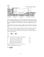
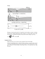
The flow splitter represents an obstruction in an open channel, typically the pier of a
bridge, the support structure on the top of a dam spillway etc. The effect of the
obstruction is similar to a constriction but the flow is split into two streams instead of
one.
The obstruction causes a disturbance to the flow and turbulence is created where the two
streams mix resulting in head loss. This head loss also produces a force on the object
known as form drag.
The magnitude of the losses and forces depends on the shape of the obstruction and the
degree of narrowing of the channel.
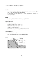
The objective is to view the disturbances caused by the splitter and to determine the
headloss/discharge characteristics.
The performance of an obstruction can be defined by the d’Aubuisson formula which
states:
(
)
2
1
2
0
2
2
1
A
v
h
g
2
y
b
K
Q
+
=
where:
Q
= Volume flowrate
(m
3
s
-1
)
K
A
= Coefficient of contraction
(Dimensionless)
b
1
= Remaining width of channel at obstruction
(m)
y
2
= Depth of flow downstream of obstruction
(m)
h
2
= Height of backwater = y
0
-y
2
(m)
v
0
= Mean upstream velocity
(m)
g
= Gravitational constant
(9.81m s
-2
)
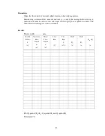
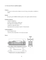
Equipment Set Up
Ensure the flume is level, with no stop logs installed at the discharge end of the channel.
Measure the width of the channel b
0
(m) and the thickness of the splitter t (m).
Position the model flow splitter mid way along the channel with the rounded end
upstream. Use Plasticine to form a smooth transition at each end of the base plate.
Position two hook and point level gauges on the channel sides, one upstream of the
splitter and one downstream of the splitter, each with the point fitted. The datum for all
measurements will be the bed of the flume. Carefully adjust the level gauges to coincide
with the bed of the flume and record the datum readings.
Содержание C4-MKII
Страница 1: ...An ISO 9001 Company INSTRUCTION MANUAL C4 MKII ISSUE 7 SEPTEMBER 2006 MULTI PURPOSE TEACHING FLUME...
Страница 2: ......
Страница 8: ......
Страница 10: ...8 1 1 Diagram 1 Inlet End of Flume 1 2 3 5 6 8 7 4...
Страница 11: ...9 1 2 Diagram 2 Discharge End of Flume 10 3 1 8 2 7 9 11...
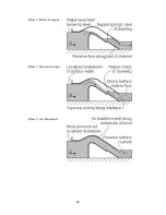
Страница 82: ...80 Phase 2 Deflected nappe Phase 3 Depressed nappe Phase 4 Air Partialised...


