


10
2 Description
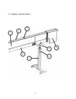
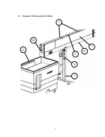
Numerical references refer to the drawings on pages 8 and 9.
2.1
Overview
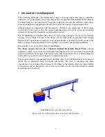
The flume consists of a clear-sided rectangular working section supported on a frame,
with an inlet tank at one end. The frame is supported on pedestals, and a jack allows the
flume to be tilted. The flume is designed to be used with an Armfield F1-10 Hydraulics
Bench, which provides a re-circulating water supply and a volumetric measuring facility.
2.2
Working Section
The working section of the channel (1), which is open at the top, consists of clear acrylic
sides which are sealed to a bed (8) fabricated from painted aluminium alloy. The clear
sides allow full visualisation of the flow conditions inside the working section. Spacers
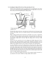
(3) across the top edges of the sides ensure that the flume sides remain rigid. The bed of
the working section incorporates pressure tappings with isolating valves and model
mounting points (See section 3.2 for further information). Two carriers (2), mounted
across the top edges of the channel walls, allow hook and point level gauges to be used to
measure the depth of water at any position along the length of the working section. See
section 2.6.
2.3
Inlet Tank
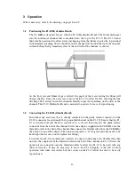
Water enters the parallel working section via the inlet tank (4) that is constructed from
PVC. The water pipe entering the inlet tank has diffused outlets and the water flows
through a diffuser and a perforated plate to reduce any turbulence in the water and
produce a smooth flow of water into the working section of the channel.
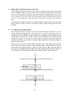
2.4
Overshot Weir
The level in the working section of the flume may be controlled by an overshot weir
arrangement at the exit (10) consisting of stop logs in a slot. Stop logs are simply added
or taken away to provide the required depth of water in the working section. Water
exiting from the channel discharges into the moulded channel on top of the F1-10
Hydraulics Bench (11) where it returns by gravity to the sump tank via the volumetric
measuring tank.
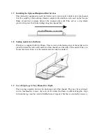
2.5
Optional Flowmeter
An optional shunt type flowmeter (9) can be supplied with the flume to provide a direct
reading of the volume flowrate of the water passing through the working section of the
flume. This provides a convenient means of setting up the various open channel
demonstrations without the need for repeated timings using a stopwatch. When supplied
this flowmeter is mounted on the pivot pedestal of the flume and consists of a variable
Содержание C4-MKII
Страница 1: ...An ISO 9001 Company INSTRUCTION MANUAL C4 MKII ISSUE 7 SEPTEMBER 2006 MULTI PURPOSE TEACHING FLUME...
Страница 2: ......
Страница 8: ......
Страница 10: ...8 1 1 Diagram 1 Inlet End of Flume 1 2 3 5 6 8 7 4...
Страница 11: ...9 1 2 Diagram 2 Discharge End of Flume 10 3 1 8 2 7 9 11...
Страница 82: ...80 Phase 2 Deflected nappe Phase 3 Depressed nappe Phase 4 Air Partialised...


