


43
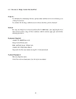
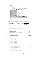
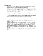
Procedure
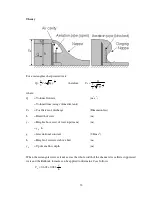
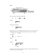
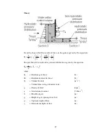
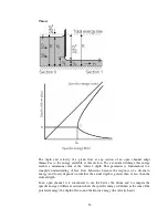
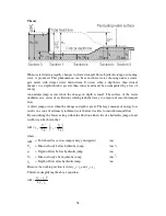
Open the flow control valve and allow the water to flow into the flume then adjust the
valve to obtain a depth y
0
of 0.070m upstream of the weir. Maintain this level whilst
measuring the downstream depth of flow y
1
and the flowrate Q. For accurate results the
upstream level gauge must be far enough upstream to be clear of the draw-down over the
weir. Similarly the downstream level gauge must be in clear water after the level has
stabilised.
Repeat this for 0.010m increments of y
0
, recording the measurements of y
0
, y
1
and Q and
noting any variation in the flow patterns over the weir.
Add stop logs one at a time at the discharge end of the flume. When the levels have
stabilised record the measurements of y
0
, y
1
and Q. Observe the changes in the flow
patterns over the weir.
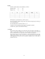
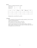
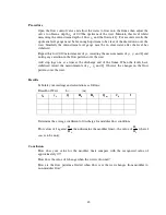
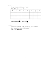
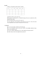
Results
Tabulate your readings and calculations as follows:
Breadth of Weir
b =…………(m)
y
0
y
1
Q
H
0
H
1
Q
m
C
d
f
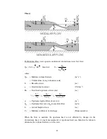
Determine the average coefficient of discharge for modular flow conditions.
Plot values of f against
0
1
H
H
then determine the modular limit – the value of
0
1
H
H
where f
ceases to be unity.
Conclusion
How does your value for the modular limit compare with the recognised value of
approximately 0.7?
How does the value of f change when the weir is drowned?
How are the flow patterns affected when flow over the weir changes from modular to
non-modular flow?
Содержание C4-MKII
Страница 1: ...An ISO 9001 Company INSTRUCTION MANUAL C4 MKII ISSUE 7 SEPTEMBER 2006 MULTI PURPOSE TEACHING FLUME...
Страница 2: ......
Страница 8: ......
Страница 10: ...8 1 1 Diagram 1 Inlet End of Flume 1 2 3 5 6 8 7 4...
Страница 11: ...9 1 2 Diagram 2 Discharge End of Flume 10 3 1 8 2 7 9 11...
Страница 82: ...80 Phase 2 Deflected nappe Phase 3 Depressed nappe Phase 4 Air Partialised...


