


70
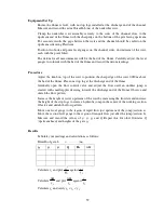
Procedure
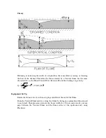
Gradually open the flow control valve and allow water to flow along the channel. Add
stop logs at the discharge end of the channel to provide a head of water which does not
totally submerge the model. Increase the flow in stages, ensuring that the model is not
submerged and at each stage observe and sketch the flow pattern around the model then
measure and record y
0
, y
2
and Q.
Repeat the above procedure with the pointed end of the flow splitter facing upstream.
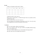
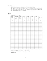
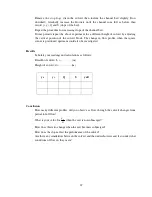
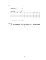
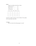
Results
Tabulate your readings and calculations as follows:
Breadth of channel,
b
0
=………….(m)
Thickness of splitter,
t
=………….(m)
b
2
= b
0
– t
=………….(m)
y
0
y
2
Q
v
0
K
A
Conclusion
Comment on the flow pattern surrounding the splitter and how it changes with increasing
fluid velocity.
What is your value for K
a
? Does the value change with increasing velocity?
What is the effect of changing the orientation (round nose/pointed nose upstream) of the
splitter?
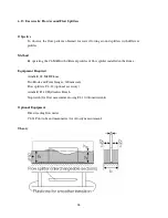
Содержание C4-MKII
Страница 1: ...An ISO 9001 Company INSTRUCTION MANUAL C4 MKII ISSUE 7 SEPTEMBER 2006 MULTI PURPOSE TEACHING FLUME...
Страница 2: ......
Страница 8: ......
Страница 10: ...8 1 1 Diagram 1 Inlet End of Flume 1 2 3 5 6 8 7 4...
Страница 11: ...9 1 2 Diagram 2 Discharge End of Flume 10 3 1 8 2 7 9 11...
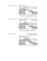
Страница 82: ...80 Phase 2 Deflected nappe Phase 3 Depressed nappe Phase 4 Air Partialised...


