


20
3.12
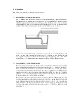
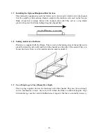
Installing the Optional Wave Generator (C4-67)
When required for use, the C4-67 Wave Generator should be mounted on top of the flow channel
inlet tank with the vertical paddle at the entrance to the working section. The Wave Generator
must be secured to the flange of the tank using the fixings supplied. Operation of the Wave
Generator involves rotating and moving parts so extreme care must be taken when using the
generator. Refer to the safety section of this instruction manual for specific notes regarding safe
operation of the Wave Generator
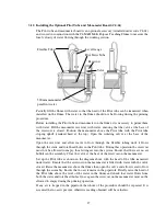
The C4-67 Wave Generator consists of a vertical paddle that is moved backwards and forwards
by a variable speed, variable stroke drive to produce water waves in the working section of the
flow channel. The drive arrangement consists of a combined motor/gearbox with an eccentric
crank wheel and connecting rod. The connecting rod can be connected to the crank wheel at
different radii to change the stroke of the paddle and thereby change the amplitude of the waves.
The speed of the drive motor is continuously adjustable to change the frequency of the waves via
the speed controller mounted on a bracket at the side.
The stop logs should be installed at the discharge end of the flume to retain the water inside the
working section when the C4-67 Wave Generator is operating.
The triangular sloping beach, supplied with the C4-67 Wave Generator, should be installed
inside the working section of the flow channel at the opposite end to the Wave Generator
(located against the stop logs). This absorbs the energy of the waves to minimise the effect of
reflected waves. The beach consists of a plastic strip with a 25mm thick fibre mat bonded to it
that allows water to flow through the material but resists the movement and absorbs the energy in
the waves
3.13
Operating the Optional Wave Generator (C4-67)
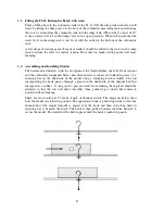
Changing the depth of the water
The depth of the water should be adjusted to suit the required demonstration. The water level
should be raised by opening the flow control valve with the F1-10 Hydraulics Bench switched
on. The water level should be lowered by opening the flow control valve with the F1-10
Hydraulics Bench switched off.
If the required depth of water is not known then the channel should be filled initially to mid
height then tested by operating the wave paddle. The level can then be adjusted up or down to
suit the demonstration. Note that insufficient water will give waves of small amplitude and
excessive depth may result in water spilling from the sides of the channel when waves are
generated.
Setting the required amplitude of the waves (stroke of the paddle)
Before making any adjustments to the stroke of the paddle the drive motor must be switched off
at the control console and the electrical supply must be disconnected.
Having checked that the electrical supply is disconnected the guard can be removed from the
drive arrangement by unscrewing the fixings.
Содержание C4-MKII
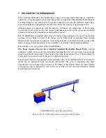
Страница 1: ...An ISO 9001 Company INSTRUCTION MANUAL C4 MKII ISSUE 7 SEPTEMBER 2006 MULTI PURPOSE TEACHING FLUME...
Страница 2: ......
Страница 8: ......
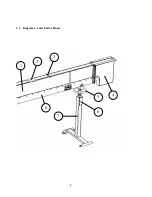
Страница 10: ...8 1 1 Diagram 1 Inlet End of Flume 1 2 3 5 6 8 7 4...
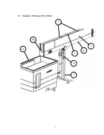
Страница 11: ...9 1 2 Diagram 2 Discharge End of Flume 10 3 1 8 2 7 9 11...
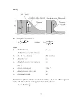
Страница 82: ...80 Phase 2 Deflected nappe Phase 3 Depressed nappe Phase 4 Air Partialised...


