5-6
Spark Plug Cap
1. Connect the red tester lead to one end of the cap;
then connect the black tester lead to the other
end of the cap.
AR603D
2. The meter reading must be within specification.
NOTE: If the meter does not read as specified,
replace the spark plug cap.
Indicator Lights
(DVX Model)
To access the indicator lights, use the following pro-
cedure.
1. Remove the two cap screws and one reinstall-
able rivet securing the instrument pod; then turn
the instrument pod over to access the indicator
lights.
2. Remove the light to be tested by pulling the bulb
socket from the light pod; then remove the bulb
from the socket.
NOTE: Bulbs must be checked by switching to a
position where the bulb is illuminated. Power to
the indicator light may be verified by installing a
working light bulb in that position.
LCD Gauge Assembly
REMOVING
To remove the LCD gauge assembly, see Section 9
of this manual.
TESTING
NOTE: If any functions (segments or displays)
are not normal or do not display as indicated, the
LCD gauge must be replaced.
1. Remove the instrument pod; then disconnect the
speedometer cable. Leave the gauge connected
to the wiring harness.
NOTE: To perform the following tests, two Maxi-
Clips (p/n 0744-041) and one jumper wire will be
required.
2. Connect the black MaxiClip to the green/black
wire.
3. Connect the red MaxiClip to the light green/red
wire; then connect the jumper between the
MaxiClips and turn the ignition switch to the
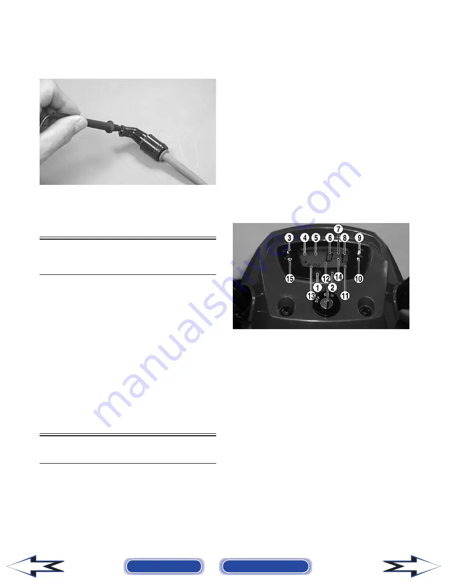
ON position. The neutral indicator light (9) must
illuminate.
KM123D
4. Connect the red MaxiClip to the blue/red wire.
The reverse indicator light (10) must illuminate.
5. Connect the red MaxiClip to the white/red wire.
The low range light (3) must illuminate.
6. Connect the red MaxiClip to the green/blue
wire. The temperature indicator (4) must indi-
cate hot (all indicator segments visible) and
begin flashing. The thermometer icon will also
flash.
7. Connect the red MaxiClip to the yellow/white
wire. The fuel quantity indicator (8) must
sequence (one segment every 8-10 seconds)
until the bottom segment begins flashing. After
flashing for 8-10 seconds, the bottom segment
will extinguish and the gas pump icon (7) will
begin flashing.
NOTE: There must be sufficient gas in the gas
tank to illuminate at least one fuel quantity indica-
tor segment.
Back to TOC
Back to Section TOC
Next
Back
Содержание DVX 250 2007
Страница 1: ......


