Back to TOC
Back to Section TOC
Next
Back
3-15
3
A. Transmission (Utility Model)
1. Drain the transmission lubricant into a suitable
container; then install the drain plug and tighten
to specifications.
KM106
NOTE: If the engine has not been removed,
remove the swing arm assembly (see Section 7).
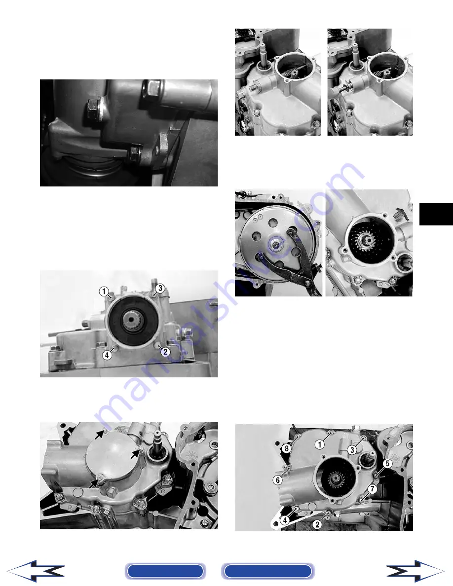
2. Using a crisscross pattern, remove four cap
screws securing the secondary driven bevel gear
assembly to the transmission case cover; then
remove the assembly. Account for an O-ring.
KM646A
3. Remove the three cap screws securing the sec-
ondary drive bevel gear cover; then remove the
cover. Account for a gasket.
KM648A
4. Remove the speedometer gear retainer nut,
washer, and speedometer gear.
KM649
5. Using a Spanner Wrench (p/n 0444-153) to hold
the centrifugal clutch housing, remove the nut
securing the secondary drive bevel gear to the
driveshaft.
KM650
NOTE: If the engine has been removed and the
left-side components are removed, install the cen-
trifugal clutch housing on the driveshaft. If the
left-side components have not been removed, see
Removing Left-Side Components in this section.
Remove only the V-belt cover.
6. Remove the eight cap screws securing the trans-
mission case cover to the transmission case;
then remove the cover. Account for a gasket (A),
the secondary drive bevel gear, washer (B), and
two alignment pins (C).
KM651A
Содержание DVX 250 2007
Страница 1: ......


