


Using the 2300-580-R Software with VectorStar ME7838G
4-5 Running the Verification Software
3659 0.8 mm Cal/Ver Kit & 2300-580-R PVS UG
PN: 10410-00327 Rev. D
4-9
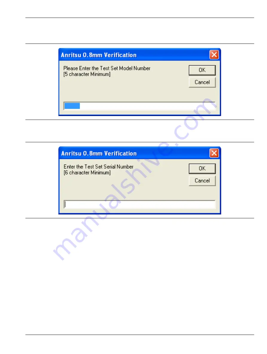
Enter Test Set Information
14.
Enter the Test Set model number and click
OK
.
15.
Enter the Test Set serial number found on the rear panel and click
OK.
16.
The program execution continues to the following
Section 4-6, “Application Interface – Setup Menu Tab”
.
Figure 4-12.
Anritsu 0.8 mm Verification Dialog – Test Set – Model Number
Figure 4-13.
Anritsu 0.8 mm Verification Dialog – Test Set – Serial Number
3739C