


CNC Setup Utility Manual
P/N 70000490C - Machine Constants
All rights reserved. Subject to change without notice.
10-December-04
2-75
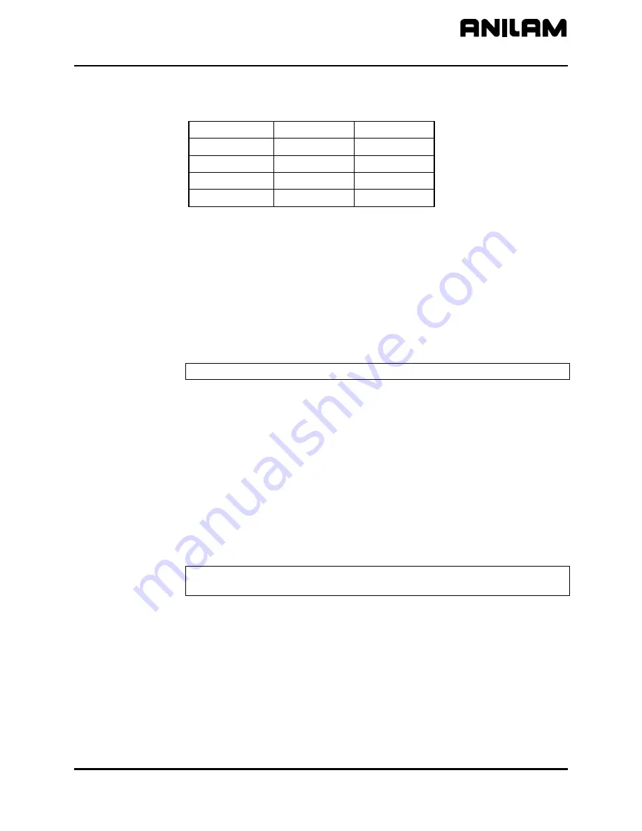
Refer to
Table 2-3
for conversion values.
Table 2-3, Micron to Inch Conversion
0.5 Micron
0.0005 mm
0.00002”
1 Micron
0.001mm
0.00005”
2 Microns
0.002mm
0.0001”
5 Microns
0.005mm
0.0002”
10 Microns
0.010mm
0.0005”
Setting In-Position Tolerance
Reference machine constant parameters:
MC_2051: X In-position Tolerance Range
MC_2151: Y In-position Tolerance Range
MC_2251: Z In-position Tolerance Range
MC_2351: U In-position Tolerance Range
NOTE:
Rapid moves always execute in
In-Position
Mode
.
When the CNC has positioned the tool within the in-position tolerance of
the target, the CNC processes the next programmed move. At this time,
the CNC displays the in-position indicator. Specify the in-position
tolerance for each enabled axis in the Setup Utility.
[Default:
0.0100 mm
]
When determining in-position tolerance:
For rotary encoders, tolerance is usually four times the machine
resolution (e.g., If machine resolution is 0.0002 in., the in-position
tolerance is 0.0008 in.). Use this as a benchmark from which to adjust
this value.
For linear encoders, tolerance equals the resolution of the linear encoder.
NOTE:
In-position tolerance must be smaller than Continuous path
tolerance.


