


CNC Setup Utility Manual
P/N 70000490C - Machine Constants
All rights reserved. Subject to change without notice.
10-December-04
2-47
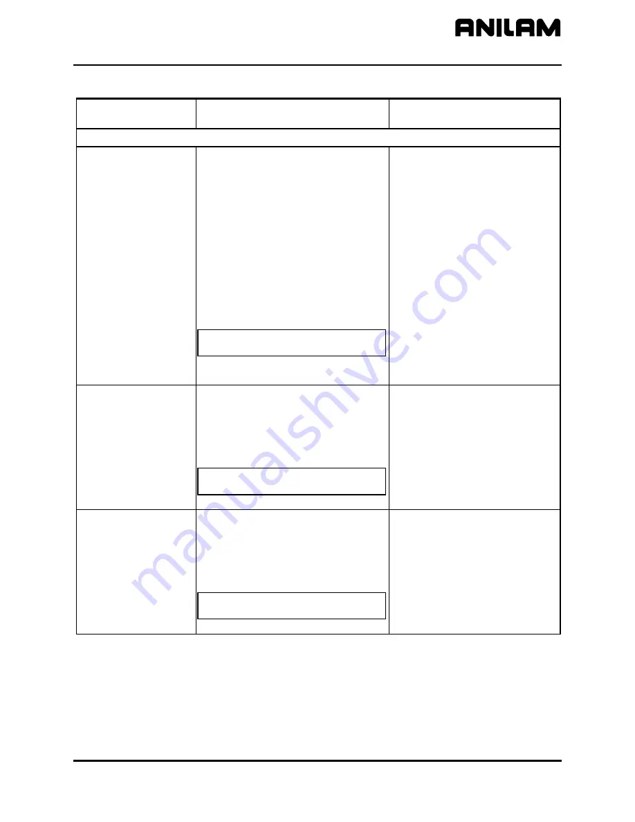
Table 2-2, Machine Constants Setup
(Continued)
Machine Constant
Parameter
Function Settings
Linear Correction Compensation Setup Parameters
MC_3000:
Linear correction
compensation
Linear correction compensation corrects
for detected mechanical errors (in the
ballscrew or elsewhere) that affect the
indicated distance displayed by the
CNC. To determine the amount of
correction required, measure the error
with a calibration device. When linear
correction is activated, the CNC
multiplies the commanded move by the
compensation value.
If you do not require linear
compensation, disable this feature.
When enabled, you can specify a
different correction value for each axis.
Correction = Distance Read by CNC ÷
Distance Actually Traveled
Enter any appropriate correction factor
from 0.300000 to 3.000000.
On (enabled)
Off
(disabled) [Default]
MC_3001:
X Linear correction
compensation
To determine the amount of X-axis
correction required, measure the error
with a calibration device. When linear
correction is activated, the CNC
multiplies the commanded move by the
compensation value.
Correction = Distance Read by CNC ÷
Distance Actually Traveled
Range (0.300000–3.000000)
1.000000 [Default]
MC_3002:
Y Linear correction
compensation
To determine the amount of Y-axis
correction required, measure the error
with a calibration device. When linear
correction is activated, the CNC
multiplies the commanded move by the
compensation value.
Correction = Distance Read by CNC ÷
Distance Actually Traveled
Range (0.300000–3.000000)
1.000000 [Default]
(Continued…)


