Commissioning
Instruction manual 91/121 V6.3
Digital outputs
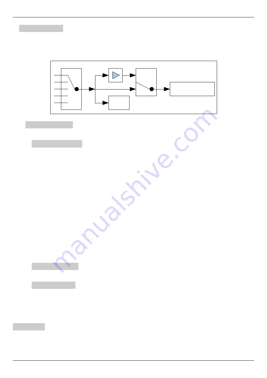
Menu group to configure and calibrate digital outputs. For simplicity it is advisable to see the following figure showing the internal
calibration structure of a generic digital output.
The logical status on the terminals of the digital output can be controlled by several selectable sources. The calibration block of the di -
gital output after reading the value of the selected source allows you to select whether to send out the same selected logical state or to
reverse it logically before transfering it to the output.
Digital Output X
Menu group to configure the digital output X. Changes to the calibration values made in this group, act only on the indicated digital
output and not on the others.
Dig.Op. X source
Parameter that allows you to select the source of the digital output. Using the keys you can select the source from among these:
•
NOT USED: the digital output is not used and the “Value” is always FALSE.
•
ZERO SPEED: the digital output (standard on DO1) indicates when the motor is stationary.
•
MOTOR BRAKE: the digital output (standard on DO2) controls the release of the motor brake.
•
MOTOR TEMP: The digital output (standard on DO3) indicates the intervention of the PTC probe mounted inside the motor
and connected to the appropriate terminals of the drive (see paragraph ”Connector X3“ on page 14).
•
DRIVE RUNNING: the digital output indicates that the drive is enabled and is running and therefore the motor is powered.
•
DC BUS CHARGED: the digital output indicates that the DC BUS has reached the right voltage and that the precharge of
the capacitors is finished.
•
SPEED THRESH. 1: the digital output (standard on DO4) indicates that the motor has exceeded the speed set in threshold 1.
To change the value of the threshold see paragraph ”Speed threshold“ on page 63.
•
PEAK MOT. LOAD: the digital output indicates that the motor is at more than 90 % of the maximum torque and that the
load needs to be reduced.
•
SPEED REACHED: the digital output indicates that the motor speed is the same as that required. For this report you can set
a reporting tolerance with the parameter indicated in paragraph ”Speed reached“ on page 47.
•
MotOvl PREWARN: The digital output indicates the condition of "Pre Warning" of the ”Motor Overload Function“ (see
page 66).
•
MotOvl WARNING: The digital output indicates the condition of "Warning" of the ”Motor Overload Function“ (see page
66).
Dig.Op. X Value
Read-only parameter that indicates the logical state of the selected source in the compensation block of the digital output. See drawing
18 for more clarity.
Dig.Op. X Sign
With this parameter you can select whether to reverse the read logical state from the source of the block or to leave it as originally.
The possible selections are:
•
NORMAL: The digital output is identical to the logical state of the associated source.
•
REVERSE: The digital output is logically reversed with respect to the logical state of the associated source
See Drawing 18 for more clarity.
Diagnostic
Menu group with read-only parameters for diagnostics or other information.
44
Alter Elettronica s.r.l.
Drawing 18 Digital Output Structure
Digital Output X
False/True → 0/+24V
VALUE
REVERSE
NORM
SIGN
Source selector


