Instruction manual 91/121 V6.3
Commissioning
There are also two possibilities to protect the motor from overloading for too long: the automatic blocking of the drive and the auto-
matic limitation of the current; both modes can be activated separately in the menu.
With
Drive Fault
activated, the drive goes into block (opens the DOK contact) and signals an alarm on the display, when the motor is
overloaded for a longer time than set in the “Overload Time“ parameter (see page 49).
With
Autom.Curr.Lim.
activated, when the motor is overloaded for a longer time than set in the parameter ”Overload Time“ (see
page 49), the drive reduces the motor current to the value set as nominal current (parameter ”Continuous service Current“ page 36)
and keeps the limiter activated until the motor current drops below 90 % of the rated current. From that moment the drive restores the
current limit equal to the maximum current (parameter ”Maximum Current“ page 36). If the overload occurs again for a longer time
than the set time, the limiter is still activated with the same features just mentioned. When the drive is limiting the current in the mo-
tor, a ”Motor Overload Limit activated“ signal appears on the display (see page 76) for as long as the limiter remains active.
5.6.10 Summing block
5.6.10.1 Generality
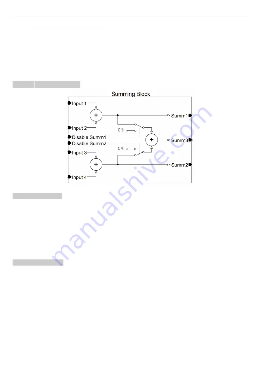
This function is used to add 4 analog signals to groups of two, and to output the 3 sum values. With reference to drawing 23 we can
find:
•
Input 1
÷ 4
: It is the input signals to the block that come from the sources that have been selected. These values are added to-
gether as shown in the drawing.
•
Disable Summ1
: it can be controlled by a digital input to disable the sending of the sum 1 result to the summation 3 (as can
be seen from the drawing). In rest condition (or with no associated digital input) the sum 1 value is sent to the summation 3.
•
Disable Summ2
: it can be controlled by a digital input to disable the sending of the sum 2 result to the summation 3 (as can
be seen from the drawing). In rest condition (or with no associated digital input) the sum 2 value is sent to the summation 3.
•
Summ1 ÷ 3
: they are the output signals from their summaries, as you can see from the drawing, and can be selected as signal
sources from some function blocks (for example: analog outputs, speed ramp, torque limit).
5.6.10.2 Calibration
This function does not need calibration. To use it you must set the sources that will have to provide the signals in the inputs of the
summaries (Analog inputs or Analog reference) and from the selection menu of the destination of the desired input go to select the
item “Inp.X SumBlock”.
Analog inputs have an Offset and Gain parameter that can be used to adapt the signal to the summing block as needed.
The results of the sums (Summ1, Summ2, Summ3) can be sent to the selected destination.
If you need to reset an external command reference, you can use one of the “DisableSumm” inputs by associating them with a digital
input.
Alter Elettronica s.r.l.
67
Drawing 23: Summing block


