Instruction manual 91/121 V6.3
Installation
4
H
Connecting cable “H” pole
4.4.6 Connector X8
Connector for optional communication cards.
4.4.7 Connector X9
Connect digital outputs.
Power supply voltage from l8Vcc to 30Vcc (nominal 24Vc.c.)
States of exits:
Off = Floating
On = Connected to +24V power supply (D24) (marked by the lighting of the corresponding led)
Maximum current for each output 100 mA, voltage drop inside the maximum current 2V.
Without service power all outputs are OFF.
In case of overload or short circuit on one or more outputs, all outputs are permanently forced into the OFF state.
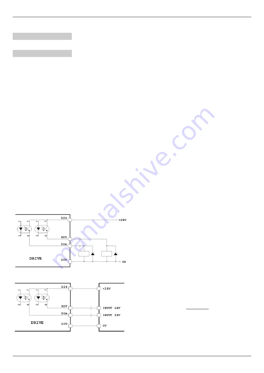
For connections please refer to Drawing 6 and Drawing 7 from page 17.
Signal allocation to PINs:
1
DOK
Digital output ”Drive OK”. It indicates that there are no alarms that prevent the drive from working and that it has
finished the peripheral initialisation phase.
Further information can be found in paragraph ”Alarm messages“ on page 70.
2
RDY
“Ready“ digital output. It signals that the drive is ready for operation and is therefore able to perform the com-
mands. See also paragraph ”RDY (Ready)“on page 69.
3
DO1
Digital output 1 programmable.
It is normally used to signal ”Zero Speed“ i.e. that the motor is stationary.
4
DO2
Digital output 2 programmable.
It is normally used to control the release of the parking brake of the motor.
5
DO3
Digital output 3 programmable.
It is normally used to signal over-temperature of the motor using the PTC probe connected to the terminals of the
X3 connector or directly on the X4.
6
DO4
Digital output 4 programmable.
It is normally used to signal the achievement of a speed threshold.
7
D24
Common to connect to +24Vcc for digital outputs.
8
+24V
24Vcc
±20 % – 100mA max.
Below are some drawings to explain the correct connections to the X9 connector:
Relay connection to receive signals from the digital outputs of the
drive.
It is necessary to connect the D24 to a power 24Vcc and
the D0V to 0V.
Connection of a
PLC
to receive signals from the drive.
The digital inputs of the PLC must receive a voltage of 24Vcc.
It is necessary to connect the PLC +24V power supply with the
D24 of the drive and the 0V of the PLC with the D0V of the
drive.
Alter Elettronica s.r.l.
17
Drawing 7
Drawing 6


